Pressure and temperature balancing valve system for a roman rub

a technology of pressure and temperature balancing and valve system, which is applied in temperatue control, process and machine control, instruments, etc., can solve the problems of infant scalding, water temperature at the sprayer, and more acute problems

Inactive Publication Date: 2009-01-15
GLOODT CARY E
View PDF6 Cites 9 Cited by
  • Summary
  • Abstract
  • Description
  • Claims
  • Application Information

AI Technical Summary

Problems solved by technology

The problem is even more acute if the bather is an infant being washed by an adult; if the adult forgets to test the water from the sprayer, the infant may be scalded.
Further, even if the water temperature is properly balanced through a mixture of hot and cold water, a sudden drain on the cold water supply (such as through flushing a toilet or the like) may suddenly allow the water temperature at the sprayer to increase sufficiently to scald.
Moreover, there is always the likelihood of a bather in the bathtub inadvertently opening the hot water valve and receiving a scalding blast of water through the spout and / or the sprayer.
The above system has the disadvantage of requiring simultaneous control of both the hot and the cold control valves 16, 18 to achieve a desired pressure and temperature combination.
While it is not difficult to achieve either a desired water temperature or a desired water pressure in this way, achieving both at once is trickier.
In addition to the inherent difficulties of achieving a water flow having both the desired temperature and pressure, the situation is further complicated because the system ideally requires one hand to adjust the hot water valve 16, a second hand to adjust the cold water valve 18, and a third hand to manipulate the hand-held shower 10.
While thermostatic and / or pressure balancing valves are well known in the art, they have typically been too large, bulky and expensive to be readily accommodated into a hand-held shower system.

Method used


Image

  • Pressure and temperature balancing valve system for a roman rub
  • Pressure and temperature balancing valve system for a roman rub
  • Pressure and temperature balancing valve system for a roman rub

Examples


first embodiment

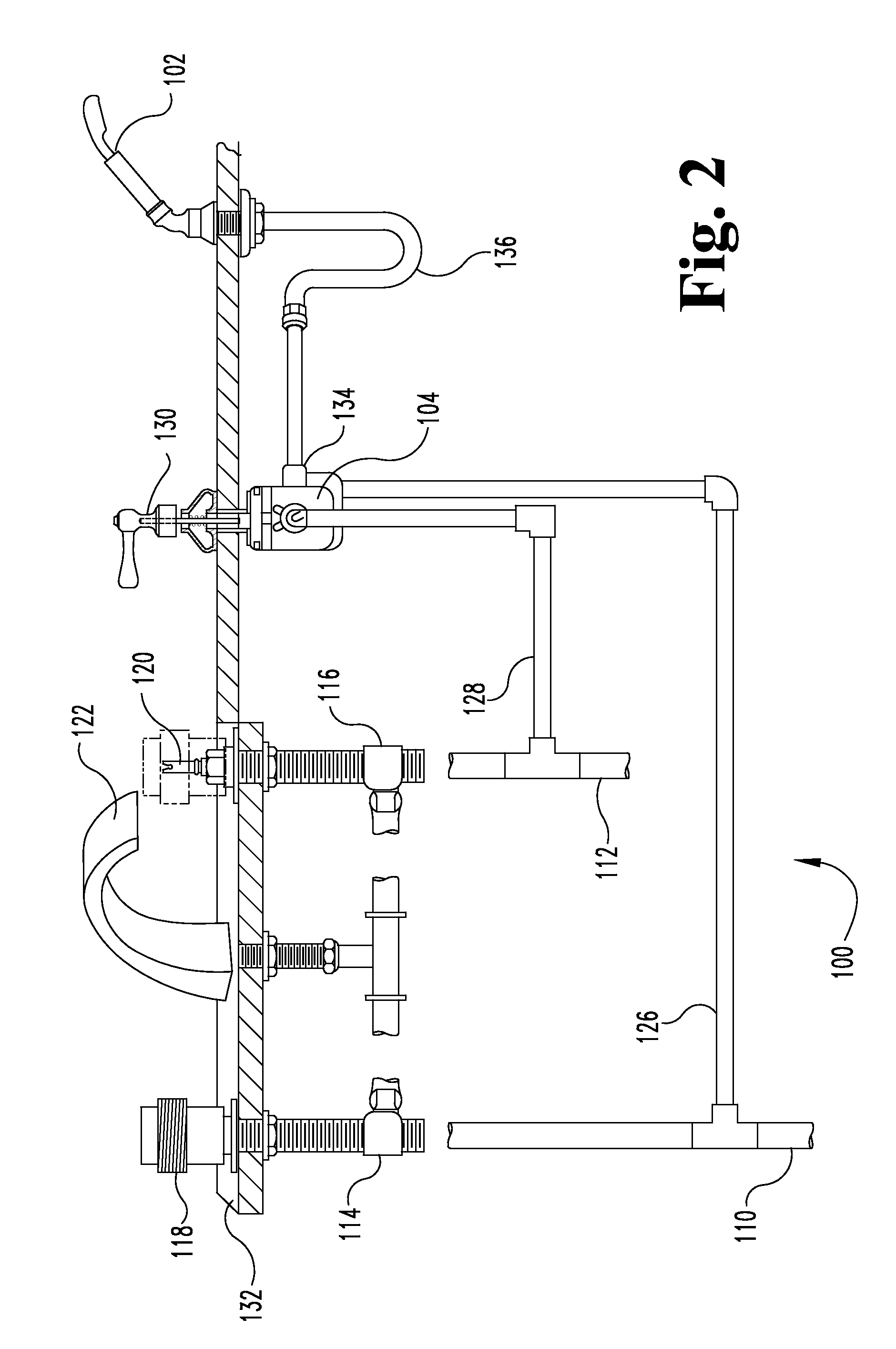
[0021]FIG. 2 schematically illustrates the present invention, a bathtub plumbing system 100 including a hand-held shower 102 controlled by an anti-scald valve 104, such as, for example and not by limitation, a Grohe temp valve, model number 34-910-000. The system 100 also includes a main hot water pipe 110 and a main cold water pipe 112 for supplying hot and cold water, respectively. The main hot water pipe 110 is connected to a hot water control valve 114 and the main cold water pipe is connected to a cold water control valve 116. The hot and cold water control valves 114, 116 are respectively operated by a hot and cold water control valve handles 118, 120. The hot and cold water control valves 114, 116 are fluidically connected to a faucet 122.

[0022]A hand-held shower hot water feed pipe 126 is fluidically connected to the main hot water pipe 110 upstream of the hot water control valve 114. A hand-held shower cold water feed pipe 128 is likewise fluidically connected to the main c...

second embodiment

[0025]FIG. 3 schematically illustrates the present invention, a bathtub plumbing system 200 including a hand-held shower 202 controlled by an anti-scald valve 204, such as, for example and not by limitation, a Lawler TMM-1000 thermostatic mixing valve. The system 200 also includes a main hot water pipe 210 and a main cold water pipe 212 for supplying hot and cold water, respectively. The main hot water pipe 210 is connected to a hot water control valve 214 and the main cold water pipe is connected to a cold water control valve 216. The hot and cold water control valves 214, 216 are respectively operated by a hot and cold water control valve handles 218, 220. The hot and cold water control valves 214, 216 are fluidically connected to a faucet 222.

[0026]A hand-held shower hot water feed pipe 226 is fluidically connected to the main hot water pipe 210 upstream of the hot water control valve 214. A hand-held shower cold water feed pipe 228 is likewise fluidically connected to the main c...

third embodiment

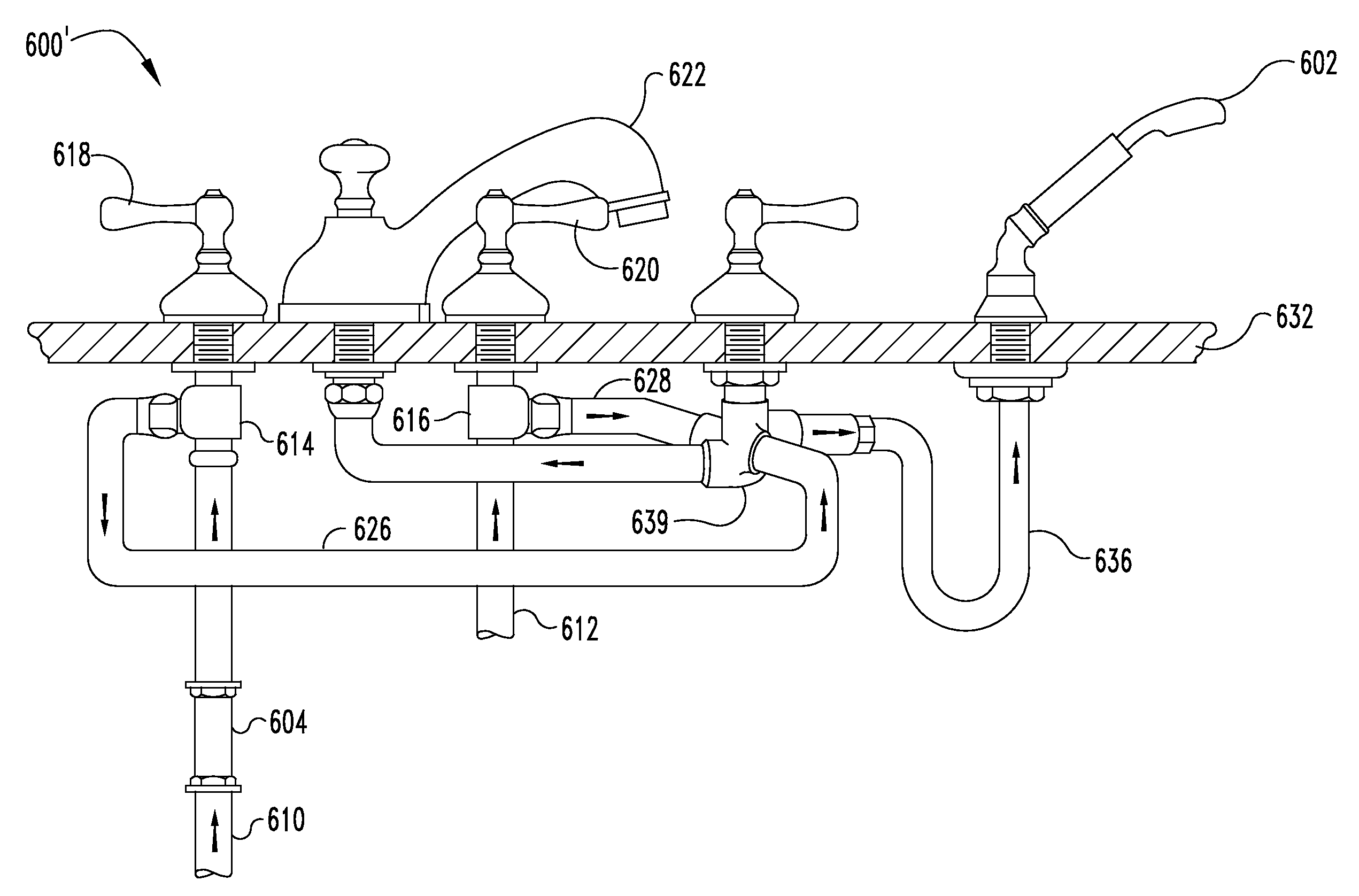
[0029]FIG. 4 schematically illustrates the present invention, a bathtub plumbing system 300 including a hand-held shower sprayer 302 fluidically connected to a pressure-balancing valve 304. Valve handle 305 is operationally connected to valve 304. The system 300 also includes a main hot water pipe 310 and a main cold water pipe 312 hydraulically connected for supplying hot and cold water, respectively. The main hot water pipe 310 is connected to a hot water control valve 314 and the main cold water pipe is connected to a cold water control valve 316. The hot and cold water control valves 314, 316 are respectively operated by a hot and cold water control valve handles 318, 320. The hot and cold water control valves 314, 216 are fluidically connected to a faucet or fill spout 322 for filling a bathtub with water.

[0030]A hand-held shower hot water feed pipe 326 is fluidically connected to the main hot water pipe 310 upstream of the hot water control valve 314. A hand-held shower cold w...


PUM


Abstract

A freestanding or Roman bathtub plumbing system including a bathtub filler (such as a spout and / or hand-held shower) controlled by a compact thermostatic mixing valve. The thermostatic mixing valve is installed in a bathtub plumbing set having a hand-held shower accessory. The thermostatic mixing valve receives hot and cold water from the main hot and cold water inlet pipes, respectively, located upstream of the respective hot and cold water control valves used to control the supply of water to the fillers. The hot and cold water feed pipes are each hydraulically connected to a first respective hot and cold water inlet of the thermostatic mixing valve. The bathtub fillers are hydraulically connected to the outlet of the thermostatic mixing valve, such as by a pipe or flexible hose. Hot and cold water entering the thermostatic mixing valve are mixed therein independently; water exiting the thermostatic mixing valve is characterized by a predetermined maximum temperature, such that a tub occupant will not be accidentally scalded.

Description

CROSS-REFERENCE TO RELATED APPLICATIONS[0001]This application is a Continuation of currently pending U.S. patent application Ser. No. 10 / 796,325, which claims priority to U.S. Provisional Application Ser. No. 60 / 240,609 filed Oct. 16, 2000; U.S. patent application Ser. No. 09 / 960,440, filed Sep. 21, 2001 and issued on Nov. 11, 2003 as U.S. Pat. No. 6,644,333; and U.S. patent application Ser. No. 10 / 704,086, filed Nov. 7, 2003.TECHNICAL FIELD OF THE INVENTION[0002]The present invention relates generally to bathtub plumbing systems and, more particularly, to a plumbing system mounted under the deck of a freestanding or Roman bathtub including an anti-scald feature fluidically connected to the tub-filling water outlet(s) and controlled by a pressure and / or volume and / or temperature controlled mixing valve.BACKGROUND OF THE INVENTION[0003]Freestanding or Roman bathtubs have been in use since the dawn of plumbing, and the piping and fixtures connected to Roman tubs have remained essentia...

Claims


Application Information

Patent Timeline
Patent Type & Authority Applications(United States)
IPC IPC(8): H05B1/02E03C1/04G05D23/13
CPCE03C1/04G05D23/1306E03C2201/30
Inventor GLOODT, CARY E.
Owner GLOODT CARY E
Why Eureka
Try Eureka