Ultrasonic handpiece

a handpiece and ultrasonic technology, applied in the field of ultrasonic fusion technology, can solve the problems of not being reliable and reliable in the distribution of fixation cement within the portion of the bone at the tip of the bone screw, and achieve the effect of reliable and even augmentation of the bone screw

Active Publication Date: 2009-01-15
WOODWELDING +1
View PDF10 Cites 28 Cited by
  • Summary
  • Abstract
  • Description
  • Claims
  • Application Information

AI Technical Summary

Benefits of technology

[0006]An aspect of the invention is to define a device and a method by which a reliable and even augmentation of a bone screw at an implantation site in the bone can now be assured.

Problems solved by technology

This system has the drawback that the manual pressure applied to the fixation cement varies, not only basically from application to application but also during the application itself so that the distribution of the fixation cement within the portion of the bone at the tip of the bone screw is neither reliable nor even.

Method used


Image

  • Ultrasonic handpiece
  • Ultrasonic handpiece

Examples


Embodiment Construction

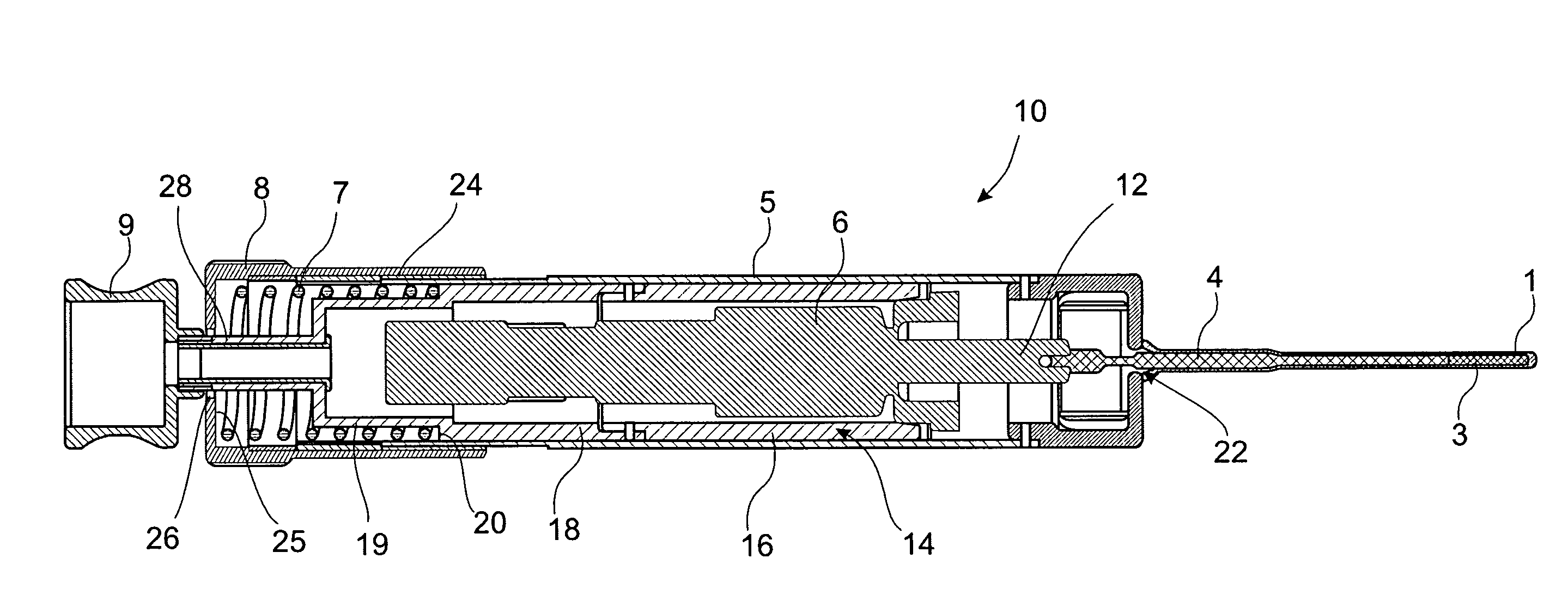
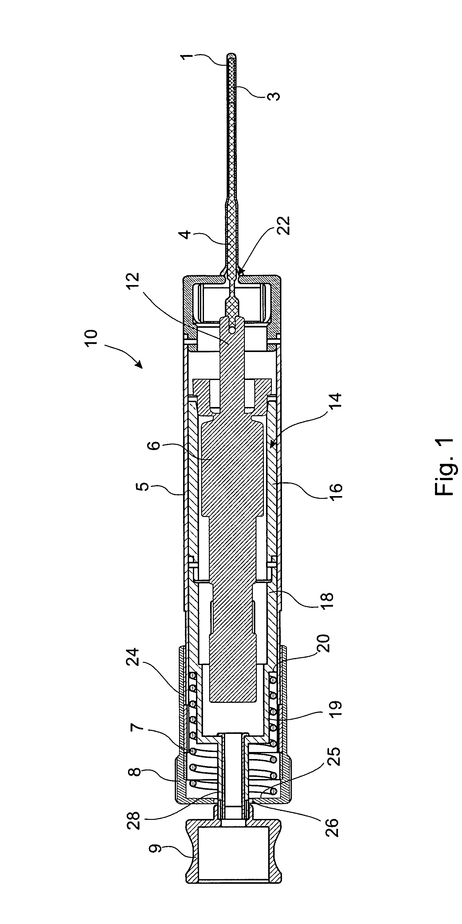
[0010]Referring now to FIG. 1 there is illustrated an ultrasonic handpiece in accordance with a preferred embodiment of the invention generally denoted as 10. The core element of the ultrasonic handpiece is an ultrasonic converter 6. This converter is electrically powered, receiving either line power or rechargeable as well as not rechargeable battery power (not shown). At its one end the converter features a tip 12 which is caused to vibrate by means of converter 6. To transmit the vibrations to an element located remote from the ultrasonic handpiece a sonotrode 4 is secured to tip 12.

[0011]The body of the converter 6 is accommodated in a two-piece housing 14. The one part 16 of the converter housing 14 adjoining tip 12 is connected to the converter body and the other part 18 of body 14 which closes off the converter body comprises at its outer side a step 20 mounting one end of an elastic element such as a coil spring 7 in the axial direction of the converter. This spring also rec...


PUM


Abstract

An ultrasonic handpiece is used for augmenting a bone screw. The handpieces comprise a housing, an ultrasonic converter shiftingly accommodated in the housing, and a sonotrode connected to one end of the ultrasonic converter. The sonotrode protrudes from the housing into the bone screw. An adjuster wheel is adjustably connected to the housing. A spring is provided the ends of which are supported by the ultrasonic converter and the adjuster wheel, respectively. The ultrasonic converter is preloaded in the direction away from the adjuster wheel by setting the adjuster wheel, thereby the sonotrode is urged with a selected force into the bone screw and the augmentation material is pressed out of the bone screw and into the bone.

Description

BACKGROUND OF THE INVENTION[0001]The invention relates in general to sonic fusion technology, it relating more particularly to an ultrasonic handpiece and a method for use thereof.[0002]Known from U.S. Pat. No. 4,653,489 is a system wherein a fixation cement is introduced through a bone screw into a portion of a bone afflicted by osteoporosis. Femoral neck fractures as well as distal femoral fractures can be fixated by means of this system.[0003]The system in accordance with prior art comprises a bone screw having a flow cavity, i.e. an axial through bore through which bone cement can be introduced into the portion at the tip of the screw. The bone cement is advanced by a device which is releasably attached to the trailing end of the screw. This device is similar to a commercially available syringe in comprising substantially a cylindrical barrel and a plunger. The barrel forms a cavity in which the plunger is movable to and fro.[0004]In use of this prior art device the fixation cem...

Claims


Application Information

Patent Timeline
Patent Type & Authority Applications(United States)
IPC IPC(8): A61N7/00A61B17/88
CPCA61B17/320068A61B17/7098A61B2017/8655A61B17/8822A61B17/864
Inventor DORAWA, KLAUSSCHWAGER, MANUEL
Owner WOODWELDING
Why Eureka
Try Eureka