

Drying method and drying device
Patent Information
- Authority / Receiving Office
- CN · China
- Patent Type
- Applications(China)
- Current Assignee / Owner
- NIPPON STEEL & SUMIKIN ENG CO LTD
- Publication Date
- 2019-12-06
Smart Images
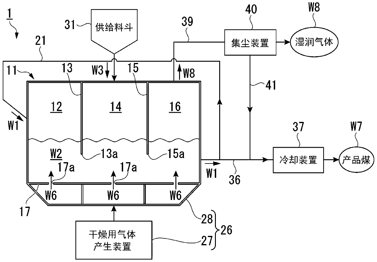
Figure 1 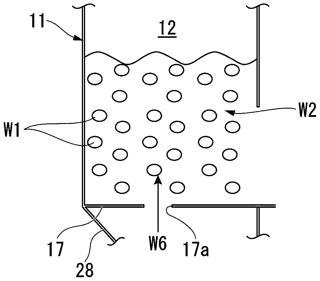
Figure 2 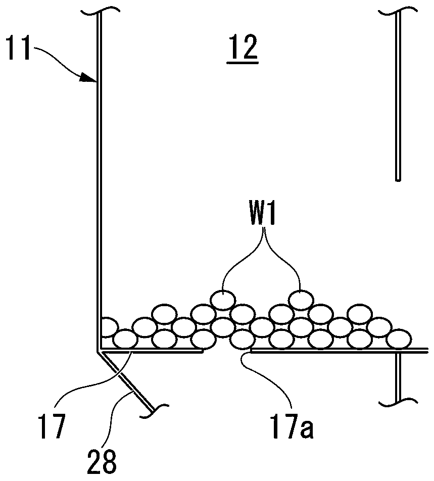
Figure 3
Abstract
Description
technical field
[0001] The invention relates to a drying method and a drying device. Background technique
[0002] Conventionally, a drying method for drying a material to be dried such as coal and sludge containing moisture has been studied.
[0003] When a high-moisture powdery object to be dried is dried in the drying chamber, the object may adhere to or remain in the drying chamber, thereby clogging the entrance of the drying chamber. Therefore, a method of suppressing the adhesion of the to-be-dried object is adopted by introducing a purge gas into the portion to which the to-be-dried object adheres.
[0004] However, in this method, it is necessary to introduce the purge gas to a plurality of places in the drying chamber, and there is a problem that the equipment cost and the running cost increase.
[0005] Therefore, in the drying method disclosed in Patent Document 1, after returning a part of the dried product (pre-dried product) obtained by drying lignite (dried ...