Substrate cleaning method and substrate cleaning apparatus

a cleaning method and substrate technology, applied in the direction of presses, cleaning using liquids, manufacturing tools, etc., can solve the problems of unsatisfactory results, particle generation, and watermark generation in the wafer periphery, and achieve the effect of adequate results

Active Publication Date: 2007-06-21
TOKYO ELECTRON LTD
View PDF3 Cites 21 Cited by
  • Summary
  • Abstract
  • Description
  • Claims
  • Application Information

AI Technical Summary

Benefits of technology

[0010] The present invention aims to provide a substrate cleaning method and a substrate cleaning apparatus, which make

Problems solved by technology

As such a sheet-fed wafer cleaning apparatus, in the case of cleaning using a hydrofluoric acid chemical, for example, the rinsing liquid in the periphery of the wafer may be shaken off in a short period by centrifugal force since the wafer front surface is hydrophobic; however, the timing of shaking off the rinsing liquid at the wafer center where the centrifugal force is small is delayed, and thus watermarks may generate in the wafer periphery that has already dried while shaking off the rinsing liquid at the center.
In addition, liquid drops may remain at the wafer center, causing particle generation.
Howe

Method used


Image

  • Substrate cleaning method and substrate cleaning apparatus
  • Substrate cleaning method and substrate cleaning apparatus
  • Substrate cleaning method and substrate cleaning apparatus

Examples


Embodiment Construction

[0032] An embodiment of the present invention is described in detail forthwith while referencing the appended drawings. A case of applying the present invention to a wafer cleaning apparatus capable of cleaning the front and back surfaces of a wafer simultaneously is described now.

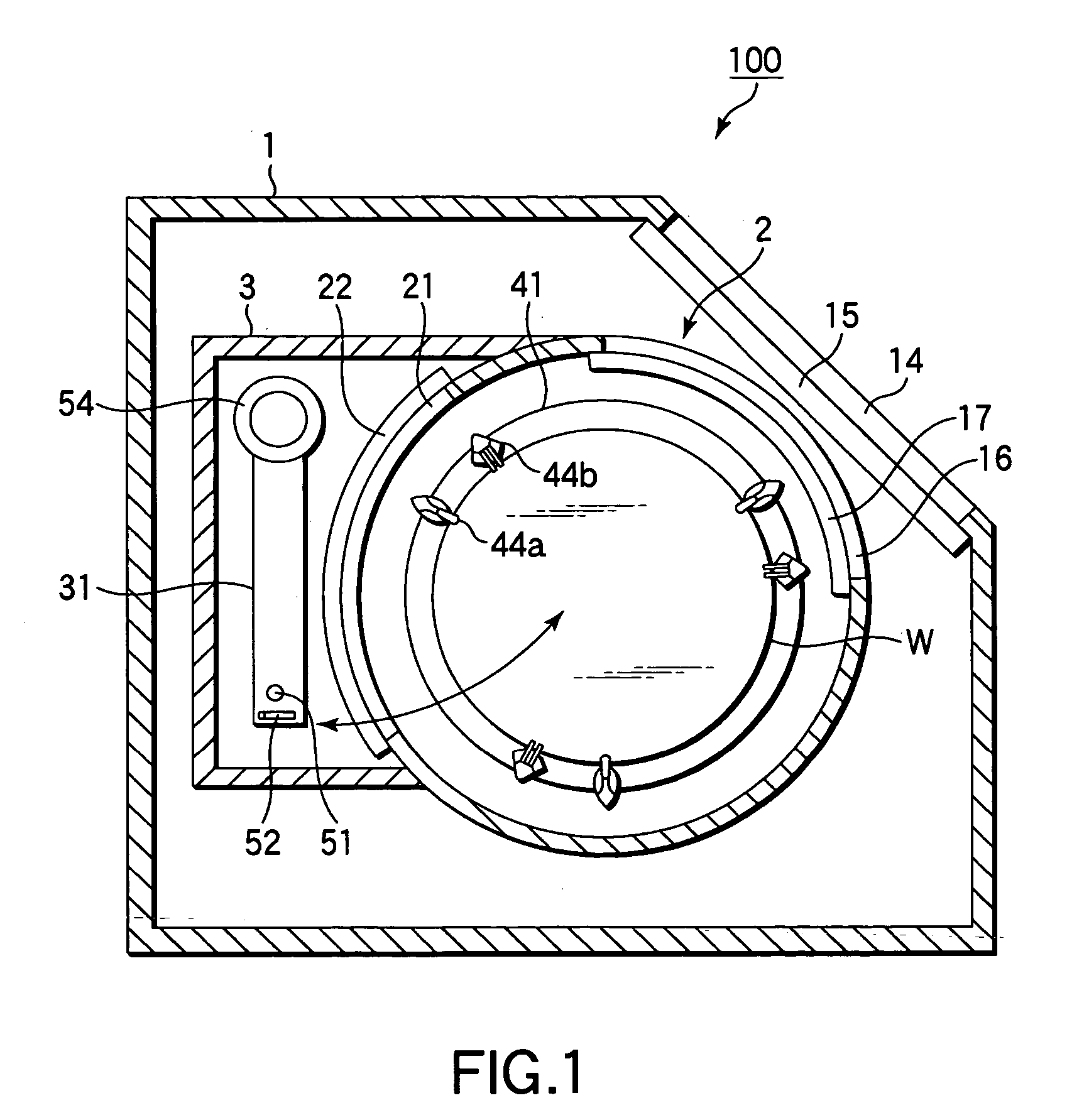
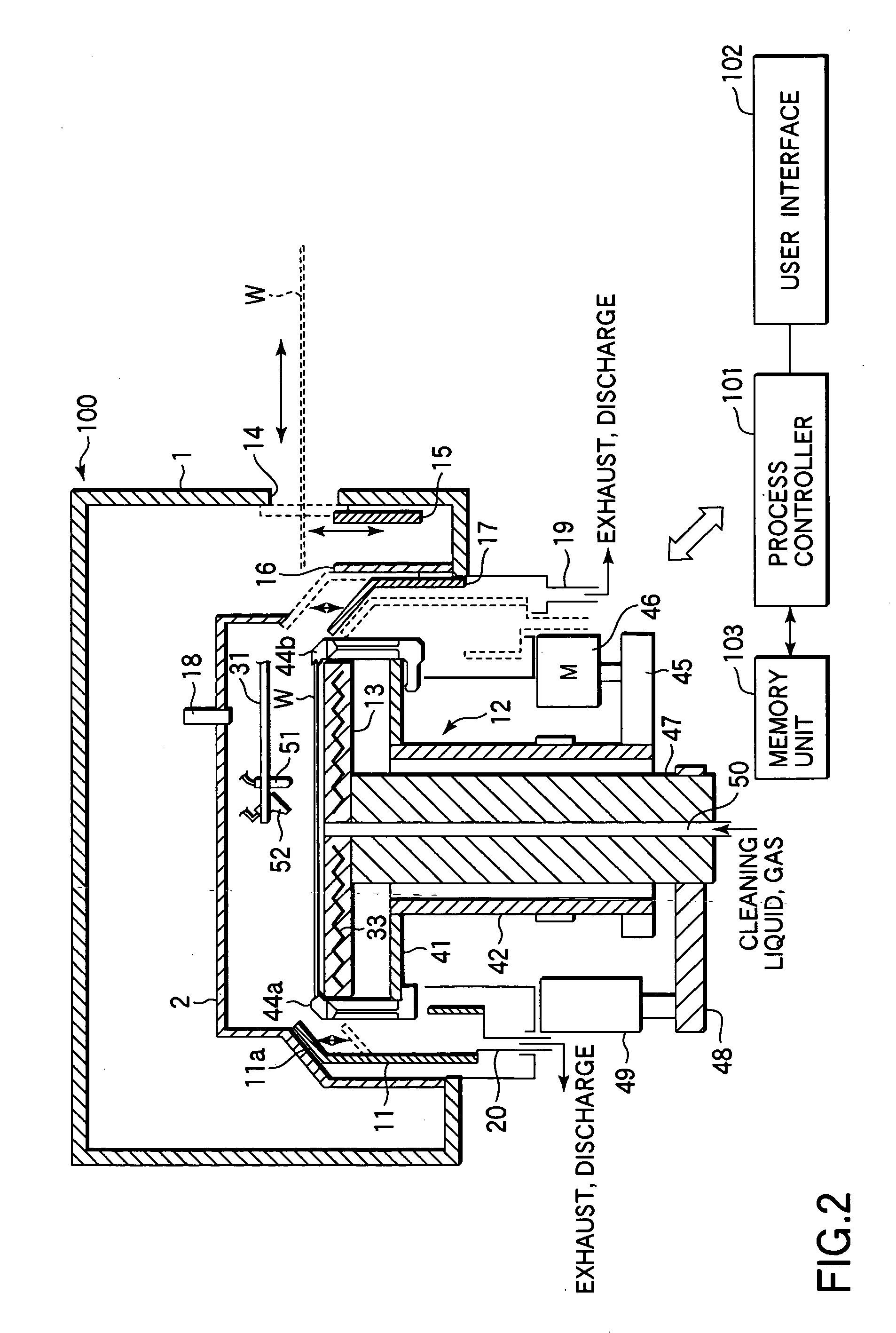
[0033]FIG. 1 is a top view schematically showing an exemplary wafer cleaning apparatus used for implementing a method according to the embodiment of the present invention, and FIG. 2 is a schematic cross section thereof. A wafer cleaning apparatus 100 has a housing 1, which includes an outer chamber 2 configured to house a wafer for cleaning, and a nozzle arm storage unit 3 configured to store a first nozzle arm 31.

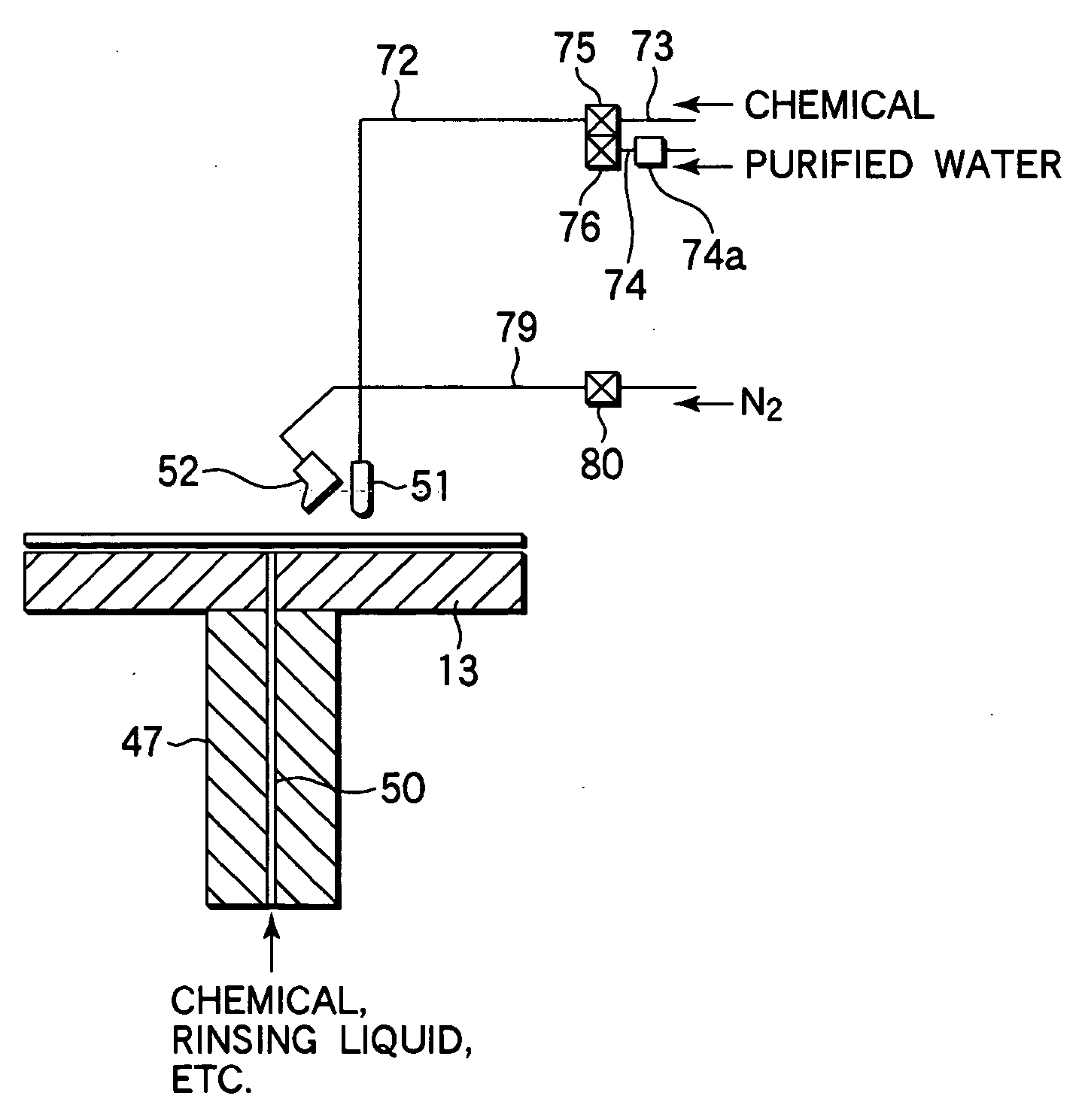
[0034] Furthermore, the wafer cleaning apparatus 100 includes an inner chamber 11 (FIG. 2), a spin chuck 12, which holds a wafer W in the inner chamber 11, and an under plate 13, which is provided capable of up and down movements and facing the back surface of the wafer W held by the spin chuc...


PUM

PropertyMeasurementUnit
Angular velocityaaaaaaaaaa

Abstract

A substrate cleaning method including rotating a substrate at least for a period, supplying a liquid to the front surface of the substrate and cleaning the substrate, and drying the substrate is provided. Said drying of the substrate includes: reducing a rotational speed of the substrate to a first rotational speed lower than a rotational speed for cleaning the substrate; starting to move a liquid supply position from approximately the center of the substrate towards a peripheral portion when the rotational speed of the substrate is reduced down to the first rotational speed; stopping liquid supply when the second rotational speed lower than the first rotational speed is reached; increasing the rotational speed from the second rotational speed; and supplying a gas towards the substrate while rotating the substrate at a higher rotational speed than the second rotational speed.

Description

BACKGROUND OF THE INVENTION [0001] 1. Field of the Invention [0002] The present invention relates to a substrate cleaning method and a substrate cleaning apparatus, which are used to clean semiconductor wafers, substrates for flat panel displays (FPDs) such as glass substrates for liquid crystal displays (LCDs), and substrates for other devices. [0003] 2. Description of the Related Art [0004] In a semiconductor device manufacturing process, a semiconductor wafer (hereafter, simply referred to as wafer) is cleaned using a predetermined chemical (cleaning liquid), and a cleaning process of removing a polymer and the like after contamination and etching processes of particles, organic contaminants, metal impurities and the like adhered to the wafer is then carried out. [0005] A sheet-fed wafer cleaning apparatus that carries out a chemical process by holding the wafer on a spin chuck, supplying a chemical onto the front and back surfaces of the wafer either at rest or spinning, supplie...

Claims


Application Information

Patent Timeline
IPC IPC(8): B08B7/00H01L21/306B30B9/00C23F1/00
CPCH01L21/02057H01L21/67028H01L21/67051H01L21/304
Inventor NANBA, HIROMITSU
Owner TOKYO ELECTRON LTD
Why Eureka
Try Eureka