Maintenance device and inkjet recording device

a technology of inkjet recording and maintenance device, which is applied in the direction of printing mechanism, printing, power drive mechanism, etc., can solve the problems of small amount of scraped ink and ink odor, and achieve the effect of hardening the ink

Pending Publication Date: 2022-02-10
KONICA MINOLTA INC
View PDF1 Cites 0 Cited by
  • Summary
  • Abstract
  • Description
  • Claims
  • Application Information

AI Technical Summary

Benefits of technology

[0006]An object of the present invention is to provide a maintenance device and an inkjet recording device that can make it harder for ink to remain in an ink receiver.

Problems solved by technology

However, an amount of scraped ink is usually small compared to an amount of ink ejected in purge maintenance.
When ink stagnates in the ink receiver, it may scatter inside the inkjet recording device and lead to contamination, or may cause ink odor.

Method used


Image

  • Maintenance device and inkjet recording device
  • Maintenance device and inkjet recording device
  • Maintenance device and inkjet recording device

Examples


modification example 1

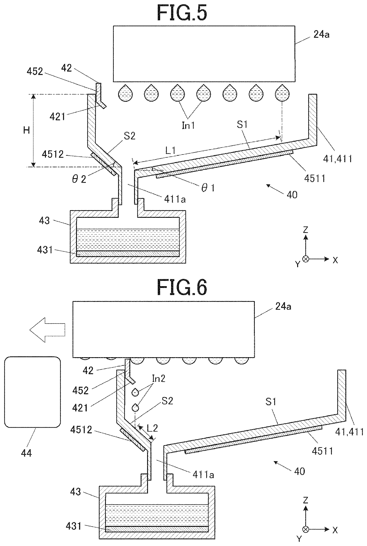
[0109]FIG. 12 shows a cross-sectional view of a configuration of the cleaner 40 in Modification Example 1.

[0110]The cleaner 40 in this modification example includes an ink sub-receiver 412 with a second face S2 that receives the scraped ink In2 separately from the ink tray 411. A scraper 42 is attached to an upper end of the ink sub-receiver 412. The second face S2 of the ink sub-receiver 412 is inclined at an angle θ2 with respect to the horizontal plane as in the above-described embodiment. A second heater 4512 that performs a heating action to heat the second face S2 on the other side of the second face S2 of the ink sub-receiver 412.

[0111]FIG. 13 shows a perspective view of the ink sub-receiver412.

[0112]The ink sub-receiver 412 has the second face S2 that receives the scraped ink In2 and side walls 412b that surrounds the second face S2. The second face S2 is in a shape whose width in the Y direction is narrower toward the lower side. An outlet 412a through which ink is dropped ...

modification example 2

[0121]FIG. 15 shows a cross-sectional view of a configuration of the cleaner 40 in Modification Example 2.

[0122]In the above-described embodiment, the inclination angle of the second face S2 is larger than that of the first face S1. However, as the flowability of ink on the second face S2 is greater than that on the first face S1, the inclination angles on the first face S1 and the second face S2 may be equal (θ1 in this example) as shown in FIG. 15. The following methods (1) to (3) can be used as a method of making the flowability of ink on the second face S2 comparatively high.

[0123](1) Method of making the surface roughness of the second face S2 smaller than that of the first face S1

[0124](2) Method of making the second face S2 more repellent to ink than the first face S1

[0125](3) Method of heating the second face S2 to a higher temperature compared to the first face S1

[0126](1) Method of Making the Surface Roughness of the Second Face S2 Smaller than that of the First Face S1

[01...


PUM


Abstract

Provided is a maintenance device that performs maintenance of a recording head with a nozzle face on which an opening of a nozzle for ink discharge is provided. The maintenance device includes a scraper that scrapes ink that adheres to the nozzle face, and an ink receiver that receives ejected ink that is ejected through the nozzle and scraped ink that is scraped off by the scraper. The ink receiver includes a first face and a second face that are each inclined with respect to a horizontal plane. The ink receiver receives the ejected ink at least on the first face of the first face and the second face, and receives the scraped ink on the second face. A flowability of ink on the second face is greater than a flowability of ink on the second face.

Description

CROSS-REFERENCE TO RELATED APPLICATIONS[0001]The present invention claims priority under 35 U.S.C. § 119 to Japanese Patent Application No. 2020-132089 filed on Aug. 4, 2020, the entire content of which is incorporated herein by reference.BACKGROUNDTechnological Field[0002]The present invention relates to a maintenance device and an inkjet recording device.Description of the Related Art[0003]Conventionally, there have been inkjet recording devices that form an image by discharging ink from nozzles of a recording head and landing the ink onto desired positions on a recording medium. There are techniques for inkjet recording devices in which image recording actions are resumed after maintenance of a recording head to suppress deterioration of the image quality due to errors in ink discharge from nozzles. Maintenance of a recording head includes, for example, purge maintenance in which ink in a recording head is ejected from nozzles and scraping maintenance in which ink adhering to a n...

Claims


Application Information

Patent Timeline
Patent Type & Authority Applications(United States)
IPC IPC(8): B41J2/165
CPCB41J2/16535B41J2/14201B41J2025/008B41J2/16588B41J2/16508B41J2/16526B41J2/16538B41J2002/16564B41J2/1721B41J2/16523
Inventor KIRIISHI, KODAI
Owner KONICA MINOLTA INC
Why Eureka
Try Eureka