Soldering apparatus and method for manufacturing electronic unit

a technology of electronic unit and soldering machine, which is applied in the direction of soldering machine, metal working machine, manufacturing tool, etc., can solve the problems of difficult to complete difficulty in properly controlling heating process, and damage to soldering iron units, etc., to achieve easy burning of attached materials, suppress thermal damage due to excessive heating, and facilitate burning of attached materials

Active Publication Date: 2020-10-27
DENSO CORP
View PDF8 Cites 0 Cited by
  • Summary
  • Abstract
  • Description
  • Claims
  • Application Information

AI Technical Summary

Benefits of technology

[0006]The present disclosure is made in view of the above problem. It is an object of the present disclosure to provide s soldering apparatus, according to which attached material is effectively removed from a soldering iron unit without causing thermal damage to the soldering apparatus.
[0011]According to the above feature of the present disclosure, the burning-assist gas is operatively supplied from the gas supply device to the soldering iron unit. For example, in the cleaning process for the soldering iron unit, since the soldering iron unit is heated and the burning-assist gas is supplied to facilitate burning of material attached to the soldering iron unit, it is possible to easily burn out the attached material. As a result, a thermal damage due to an excessive heating can be suppressed and a burning time can be shortened. Since incomplete burning of the attached material can be suppressed, the attached material hardly remains at the soldering iron unit. Accordingly, it is possible to provide the soldering apparatus, which can effectively remove the material attached to the soldering iron unit.
[0020]According to the above cleaning unit, the burning-assist gas is operatively supplied from the gas supply device to the soldering iron unit. For example, in the cleaning process for the soldering iron unit, not only the soldering iron unit is heated but also the burning-assist gas is supplied to the soldering iron unit in order to facilitate the burning of the material attached to the soldering iron unit. Therefore, it is possible to easily burn out the attached material. As a result, the thermal damage due to the excessive heating can be suppressed and the burning time can be shortened. In addition, since the incomplete burning of the attached material can be suppressed, the attached material hardly remains at the soldering iron unit. Accordingly, it is possible to effectively remove the material attached to the soldering iron unit.
[0021]In addition, according to the cleaning unit of the present disclosure, the gas to be supplied to the soldering iron unit is switched by the gas switching unit from the oxygen-rich gas to the nitrogen gas when the soldering process is carried out to the processing object. As a result, it is possible to suppress the oxidization of the solder.
[0022]On the other hand, the gas to the soldering iron unit is changed from the nitrogen gas to the oxygen-rich gas (the burning-assist gas) when the cleaning process is carried out for the soldering iron unit. As a result, it is possible to facilitate the burning of the material attached to the soldering iron unit. The nitrogen gas and the oxygen-rich gas are produced by separating the air by the gas separating unit, so that the nitrogen gas and the oxygen-rich gas are effectively supplied to the soldering iron unit. Accordingly, it is possible to effectively remove the material attached to the soldering iron unit.
[0030]According to the above feature of the present disclosure, the cleaning process is carried out for the soldering iron unit when the soldering process to the printed circuit board is stopped. In the cleaning process, the soldering iron unit is heated by the heater unit and the burning-assist gas is supplied from the gas supply device to the soldering iron unit. Since, in the cleaning process, the burning of the material attached to the soldering iron unit is facilitated by the burning-assist gas, it is possible to easily burn out the attached material. As a result, the thermal damage due to the excessive heating can be suppressed and the burning time can be shortened. In addition, since the incomplete burning of the attached material can be suppressed, the attached material hardly remains at the soldering iron unit. Since the soldering process is carried out while the influence by the attached material is suppressed, it is possible to increase quality of the electronic control unit.

Problems solved by technology

However, it is difficult to properly control the heating process by use of the two heater units.
When the soldering iron unit is heated up to a temperature higher than a necessary value, the soldering iron unit may be damaged by such a heat produced by excessively high temperature.
On the other hand, when the heating process is not sufficiently done, complete burning of the attached material may not be carried out and a part of the attached material may remain at the soldering tip.
As above, it is difficult to effectively remove the attached material from the soldering iron unit, while thermal damage to the soldering apparatus is suppressed to a small value.

Method used


Image

  • Soldering apparatus and method for manufacturing electronic unit
  • Soldering apparatus and method for manufacturing electronic unit
  • Soldering apparatus and method for manufacturing electronic unit

Examples


embodiment

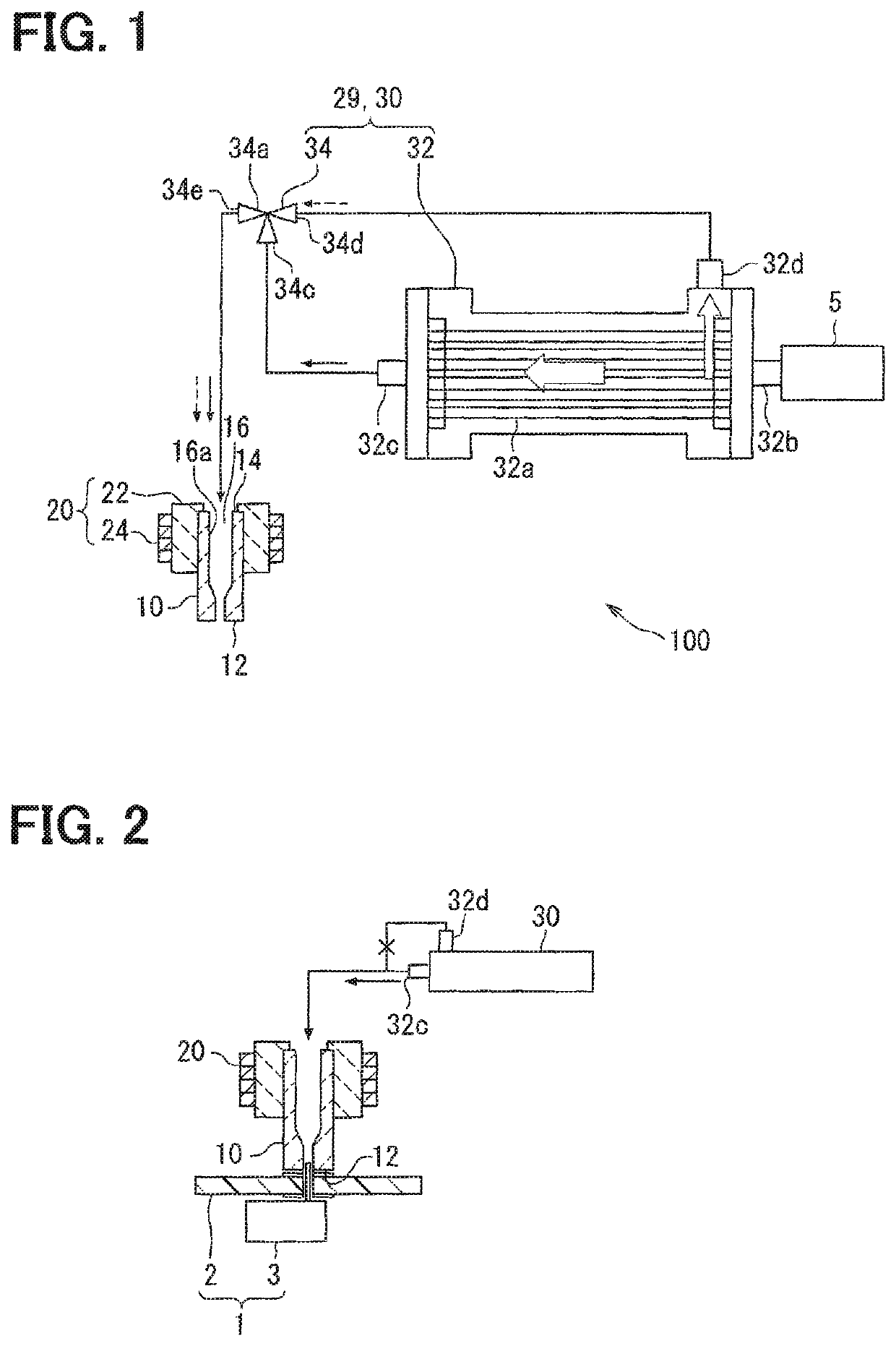
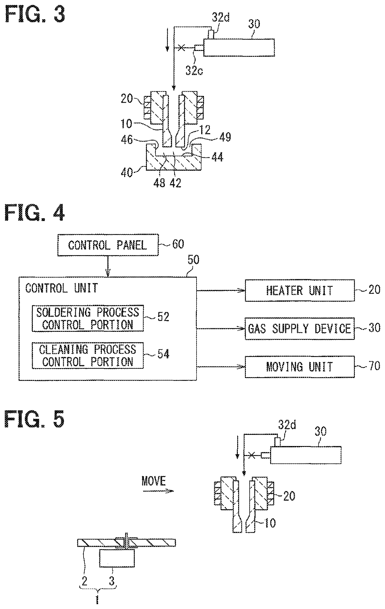
[0044]A soldering apparatus 100 shown in FIG. 1 is an apparatus for carrying out a soldering process to a printed circuit board 2 (a processing object). As shown in FIG. 2, an electronic component 3 is mounted to the printed circuit board 2 by the soldering process, so that an electronic control unit 1 for performing various kinds of controls is manufactured.

[0045]As shown in FIGS. 1 to 4, the soldering apparatus 100 is composed of a soldering iron unit 10, a heater unit 20, a gas supply device 30, a forward-end cover member 40, a control unit 50 and so on. A cleaning unit 29, which is composed of the gas supply device 30, the forward-end cover member 40 and so on, cleans the soldering iron unit 10.

[0046]The soldering iron unit 10 is made of metal having high heat conductivity. The soldering iron unit 10 may be also made of ceramic material. In the present specification, the portion 10 is referred to as the soldering iron unit 10, independently of the material of which the portion 1...

first modification

[0096]For example, as shown in FIG. 10, the gas supply device 30 has a nitrogen bomb 36 filled with nitrogen gas and an oxygen bomb 37 filled with oxygen-rich gas. The gas switching unit 34 switches the gas to be supplied to the soldering iron unit 10 from the nitrogen gas from the nitrogen bomb 36 to the oxygen-rich gas from the oxygen bomb 37, or vice versa.

second modification

[0097]As shown in FIG. 11, a cylindrical sleeve member 80 may be provided in addition to the forward-end cover member 40 in such a way that the cylindrical sleeve member 80 surrounds an outer periphery of the soldering iron unit 10 with a radial gap. The cylindrical sleeve member 80 is located at a lower-side portion of the soldering iron unit 10, at which the heater unit 20 is not located, so that the cylindrical sleeve member 80 and the heater unit 20 do not interfere with each other in the axial direction. The cylindrical sleeve member 80 is partly projected into the cylindrical hole 42 of the forward-end cover member 40 in such a way that the side wall 46 of the forward-end cover member 40 surrounds a lower-side portion of the cylindrical sleeve member 80 with a radial gap. According to the above structure, an inner space 81 is formed between the soldering iron unit 10 and the cylindrical sleeve member 80 and an outer space 82 is formed between the cylindrical sleeve member 80 a...


PUM

PropertyMeasurementUnit
flow rateaaaaaaaaaa
flow rateaaaaaaaaaa
densityaaaaaaaaaa

Abstract

A soldering apparatus has a soldering iron unit having a soldering tip for carrying out a soldering process to a printed circuit board, a heater unit for heating the soldering iron unit, and a gas supply device for operatively supplying a burning-assist gas to the soldering iron unit, when a cleaning process is carried out for the soldering iron unit. The cleaning process for the soldering iron unit is carried out when the soldering process to the printed circuit board is stopped. In the cleaning process, the soldering iron unit is heated by the heater unit and the burning-assist gas is supplied to the soldering iron unit, so that material attached to the soldering iron unit can be easily burnt out.

Description

CROSS REFERENCE TO RELATED APPLICATION[0001]This application is based on Japanese Patent Application No. 2016-218285 filed on Nov. 8, 2016, the disclosure of which is incorporated herein by reference.FIELD OF TECHNOLOGY[0002]The present disclosure relates to a soldering apparatus for carrying out a soldering process to a processing object (for example, a printed circuit board), a cleaning unit for the soldering apparatus and a method for manufacturing an electronic unit by use of the soldering apparatus.BACKGROUND[0003]A soldering apparatus is known in the art, for example, as disclosed in Japanese Patent Publication No. 2015-221449. The soldering apparatus is composed of a soldering iron unit having a soldering tip for carrying out a soldering process to a processing object, a first heater unit for heating the soldering iron unit, and so on.[0004]In addition, the soldering apparatus of the above prior art has a second heater unit, which is used for cleaning the soldering iron unit....

Claims


Application Information

Patent Timeline
Patent Type & Authority Patents(United States)
IPC IPC(8): B23K1/012B23K3/06B23K1/00H05K3/34B23K3/02B23K101/42
CPCB23K1/0016H05K3/341B23K3/028B23K1/012H05K3/3468B23K3/0638H05K3/3447H05K2203/081B23K2101/42
Inventor SHIRAISHI, SHINICHIROSUGIURA, MITSUHIROOZAWA, CHISATO
Owner DENSO CORP
Why Eureka
Try Eureka