User interface for three-dimensional navigation

a user interface and three-dimensional technology, applied in the field of patch recognition, can solve the problems of not being able to bridge the gap between static printed media (i.e., paper documents), still very difficult and/or computationally expensive to use printed documents to access or even find the electronic document from which paper documents were generated, and not being able to use such low quality images for electronic document retrieval

Active Publication Date: 2009-01-15
RICOH KK
View PDF106 Cites 46 Cited by
  • Summary
  • Abstract
  • Description
  • Claims
  • Application Information

AI Technical Summary

Problems solved by technology

Printing and copying technology has not been able to bridge the gap between static printed media (i.e., paper documents), and the “virtual world” of interactivity that includes the likes of digital communication, networking, information provision, advertising, entertainment and electronic commerce.
There continue to be problems in the prior art in bridging between the world of electronic documents on one hand and the world of paper documents on the other.
In particular, it is still very difficult and / or computationally expensive to use a printed document to access or even find the electronic document from which the paper document was generated.
A key obstacle to identifying and finding an electronic document corresponding to a printed document is the recognition of an image patch that is being captured by the camera.
While capturing an image of the printed document has become trivial with the proliferation of cell phones with cameras, there is no way to use such low quality images for electronic document retrieval.
In other words, there is not an existing method that can effectively identify from a database the document page the camera is looking at, pin-point the exact camera look-at point on the recognized page, and estimate the frame box of the image on the recognized document page.
This recognition task is made even more challenging considering that: 1) the input image is a small portion of the document page being looked at; 2) there is a large number of document pages in the database that look similar to each other; 3) the hand-held camera could have very different viewing conditions including different viewing angles and distances with respect to paper and camera motion due to hand movement; 4) there are considerable photometric changes due to lighting changes; and 5) there may be non-planar geometric deformation if the user is holding the paper by hand.
While there have been attempts in the prior art, they suffer from a number of deficiencies.
For example, a popular Scale-Invariant Feature Transform (or SIFT) is not suitable for text documents.
This makes the SIFT poor at discrimination between text and the SIFT is not stable and repeatable in noisy environments.
Other prior art approaches focus on geometric features of the text block but they are not suitable for Asian or ideographic languages.
Yet another problem with the prior art is that the few types of recognition available have discrimination capabilities that work poorly on text and image text combinations.
Often the prior art recognition methods return large number of candidate matches with no ranking or ranking that provides to many false positive matches.
One additional problem with the prior art is that there is not a method for indicating the region of an electronic document that corresponds to a query image being input.
In particular, there are not prior art methods for indicating the viewing region and a camera look at point on the electronic document.
Yet another problem with the prior art attempts to create link between paper documents and the virtual world is that there are no methods to effectively interface the virtual world using a combination of paper are computing devices.
However, there is not such interfaced for working with paper and electronic documents at the same time.

Method used


Image

  • User interface for three-dimensional navigation
  • User interface for three-dimensional navigation
  • User interface for three-dimensional navigation

Examples


second embodiment

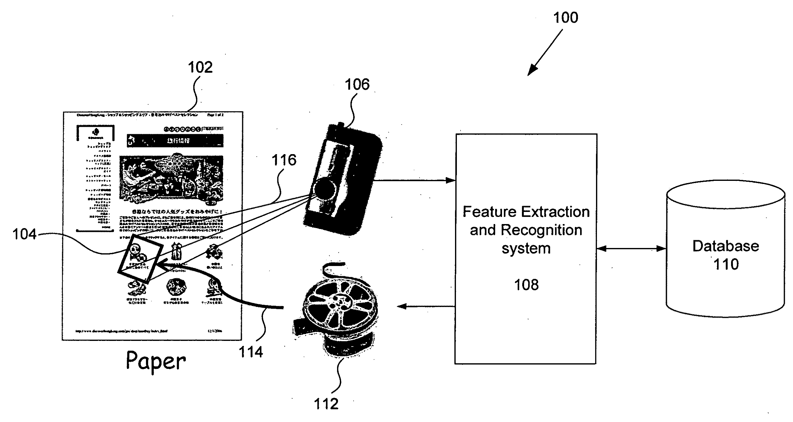
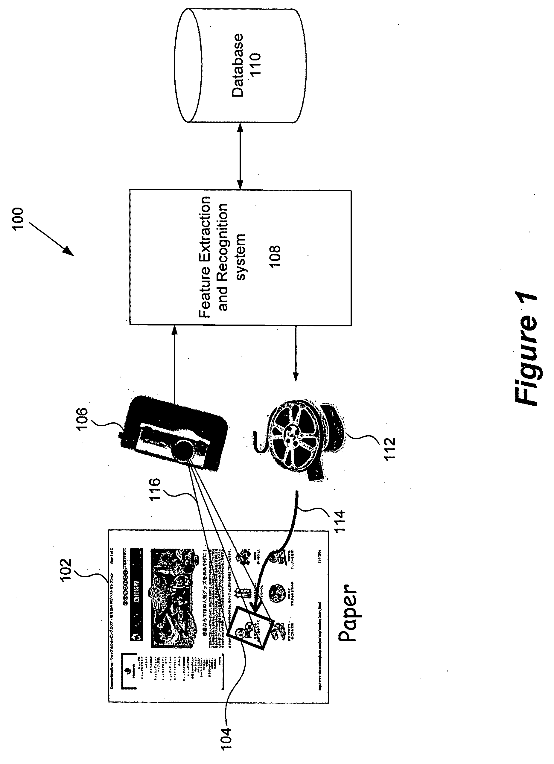
[0080]Referring now to FIG. 4, functional flow diagram of an embodiment of a feature extraction and recognition system 108 in accordance with the present invention is shown. The feature extraction and recognition system 108 includes two operational modes: a first mode in which the original electronic document is rendered and input and a feature index is stored for the invisible junction features from the input; and a second mode in which a image patch is input, and a feature description is created and used to retrieve a corresponding document, point and viewing region are output. For convenience and ease of understanding like reference numerals are used for like components having the same or similar functionality as that described above for other embodiments. This second embodiment of the system 108 includes the feature extraction unit 310, the feature indexing unit 312, the feature retrieval unit 314 and the geometric estimation unit 316.

[0081]FIG. 4 illustrates the flow of informa...

first embodiment

[0102]Where indexing is done in accordance with the first embodiment described above with reference to FIG. 7A, the feature retrieval unit 314 sends the feature points detected in the query image down to the quantization, and collects the hit lists at the leaf nodes. This produces a table of candidate document pages, along with a list of coordinates (x, y) for each candidate page. This can be send to the geometric estimation unit for further processing.

[0103]In the alternate embodiment of indexing in FIG. 7B, the retrieval process begins with the feature retrieval unit 314 receiving 802 a feature descriptor from the feature extraction unit 310. The feature retrieval unit 314 performs pattern recognition based on local features. The feature retrieval unit 314 searches for the page document whose feature points best corresponded to the feature points of the given query image patch. To establish the correspondence (in other words to recognize), the feature retrieval unit 314 recognizes...

third embodiment

[0111]FIG. 9C is a flow chart of a method for geometric estimation in accordance with the present invention. This embodiment illustrates the use of two separate geometric estimations, and their operation in parallel for increased performance. The process begins by receiving the candidate page identifications that have been identified by the feature retrieval unit 314, and then sorts 920 the candidate document pages based on the number of feature points in each candidate document page. The sorted list of candidate pages is then provided for two separate geometric estimations. One geometric estimation ranks 922 the candidate pages using feature detection with geometric constraints. For example, the rotation or orientation and scale attributes of feature detection are enforced in this geometric estimation. A second geometric estimation ranks 924 the candidate pages using a projective transformation with geometric constraints such as discussed above with reference to FIG. 9B. For exampl...


PUM


Abstract

The present invention uses invisible junctions which are a set of local features unique to every page of the electronic document to match the captured image to a part of an electronic document. The present invention includes: an image capture device, a feature extraction and recognition system and database. When an electronic document is printed, the feature extraction and recognition system captures an image of the document page. The features in the captured image are then extracted, indexed and stored in the database. Given a query image, usually a small patch of some document page captured by a low resolution image capture device, the features in the query image are extracted and compared against those stored in the database to identify the query image. The present invention also includes methods for recognizing and tracking the viewing region and look at point corresponding to the input query image. This information is combined with a rendering of the original input document to generate a new graphical user interface to the user. This user interface can be displayed on a conventional browser or even on the display of an image capture device.

Description

BACKGROUND OF THE INVENTION[0001]The present invention relates to processing techniques for patch recognition. More particularly, the present invention relates to systems and methods for using a new feature referred to herein as invisible junctions for image-based document patch recognition. Still more particularly, the present invention relates to a system and methods for using invisible junctions to provide a user interface for three-dimensional navigation.[0002]Computers and electronic documents were once restricted to use in a desktop environments where electronic documents were output by the computer to printers and printed on paper. Printers and copiers are used in private and commercial office environments, in home environments with personal computers, and in document printing and publishing service environments. Once an electronic document is printed out on paper, manipulations on these two types of documents are mostly independent. Printing and copying technology has not be...

Claims


Application Information

Patent Timeline
Patent Type & Authority Applications(United States)
IPC IPC(8): G06F3/048G06V30/10G06V30/142
CPCG06K9/228G06K9/2081G06V30/142G06V30/10G06V30/1456
Inventor KE, QIFAHART, PETER E.HULL, JONATHAN J.KISHI, HIDENOBU
Owner RICOH KK
Why Eureka
Try Eureka