Hand-held wringler

Active Publication Date: 2009-01-22
VARGA GEORGE
View PDF17 Cites 2 Cited by
  • Summary
  • Abstract
  • Description
  • Claims
  • Application Information

AI Technical Summary

Benefits of technology

[0016]It is yet another objective of the present invention to provide a hand-held wringer device without a hand-crank to minimize force.
[0017]It is yet another objective of the present invention to provide a hand-held wringer device with rollers allowing for a selective amount of force exerted by the rollers on the material passing through the two rollers.
[0018]It is yet another objective of the present invention to provide

Problems solved by technology

However, a chamois is not capable of drying an entire vehicle without having to be wrung because the chamois becomes saturated with water; thus the chamois is typically wrung out by hand multiple times and then used again to continue drying the remaining wet exterior surface of the vehicle.
Hand wringing the chamois is an effective way to expel water from the chamios but only if the user has strong hands; otherwise water is not expelled out evenly from the chamois and small areas of water will continue to remain on the chamois, thus the chamois will not perform as well as it did when it was dry.
However, a fixed wringer would not be convenient since it would be located at distance from vehicle.
Although fixed wringers on the washing machines were convenient for when washing clothes when washing a vehicle it is disadvantageous and inconvenient for the vehicle owner to have to go a remote location apart from the quarters of the user or vehicle to use the wringer.
Other disadvantages associated with the '877 device is the use of a hand crank typically becomes tiresome and the mutual contact between the rollers, which allows for maximum expelling of water from the material, is typically lost over time.
In addition, if getting to the wringer or the actual wringing takes too long, the wet vehicle which remains in the sun will begin to form water spots on the surface of the vehicle.
However, typical por

Method used


Image

  • Hand-held wringler
  • Hand-held wringler
  • Hand-held wringler

Examples


Embodiment Construction

[0027]Detailed embodiments of the instant invention are disclosed herein, however, it is to be understood that the disclosed embodiments are merely exemplary of the invention, which may be embodied in various forms. Therefore, specific functional and structural details disclosed herein are not to be interpreted as limiting, but merely as a basis for the claims and as a representation basis for teaching one skilled in the art to variously employ the present invention in virtually any appropriately detailed structure.

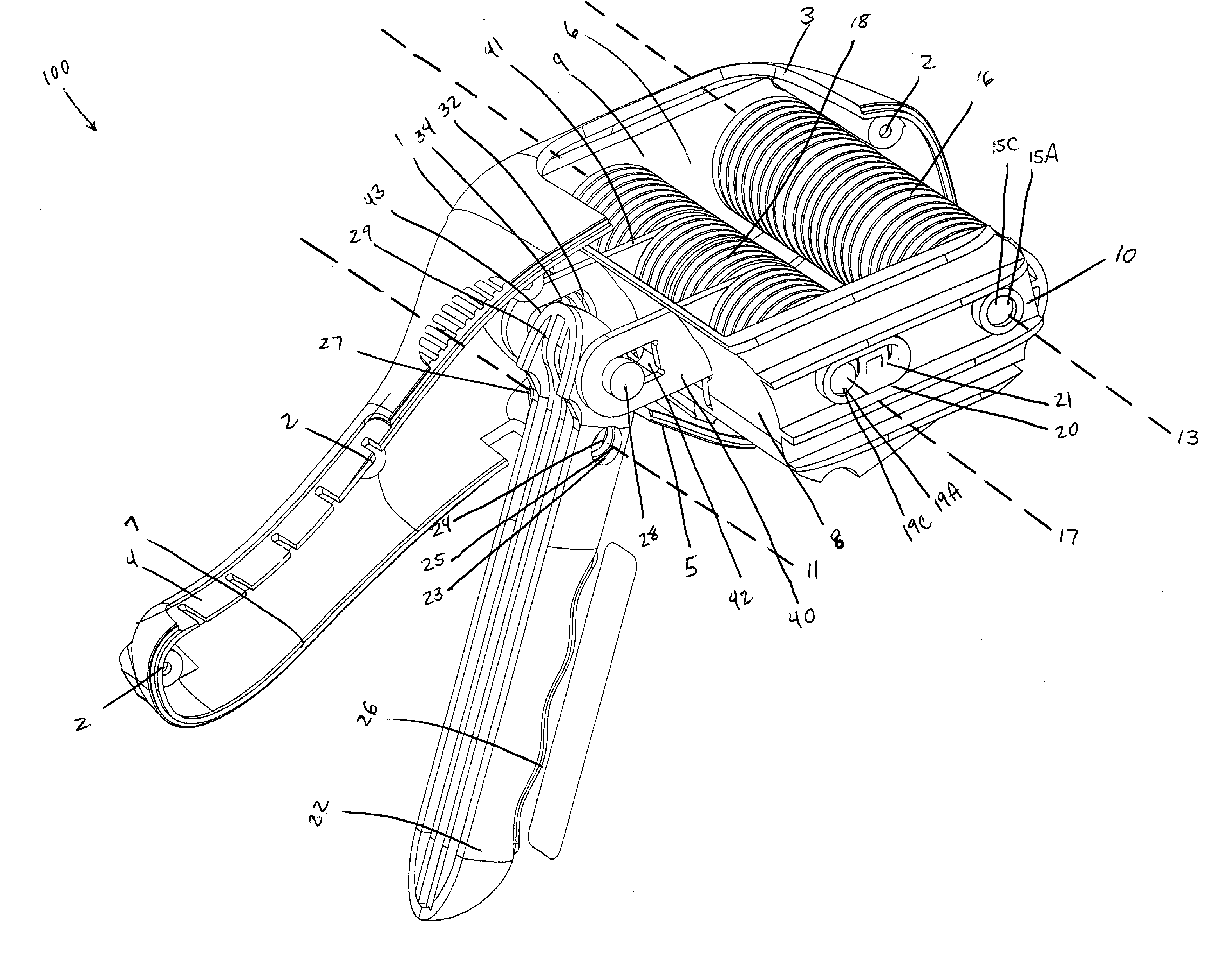
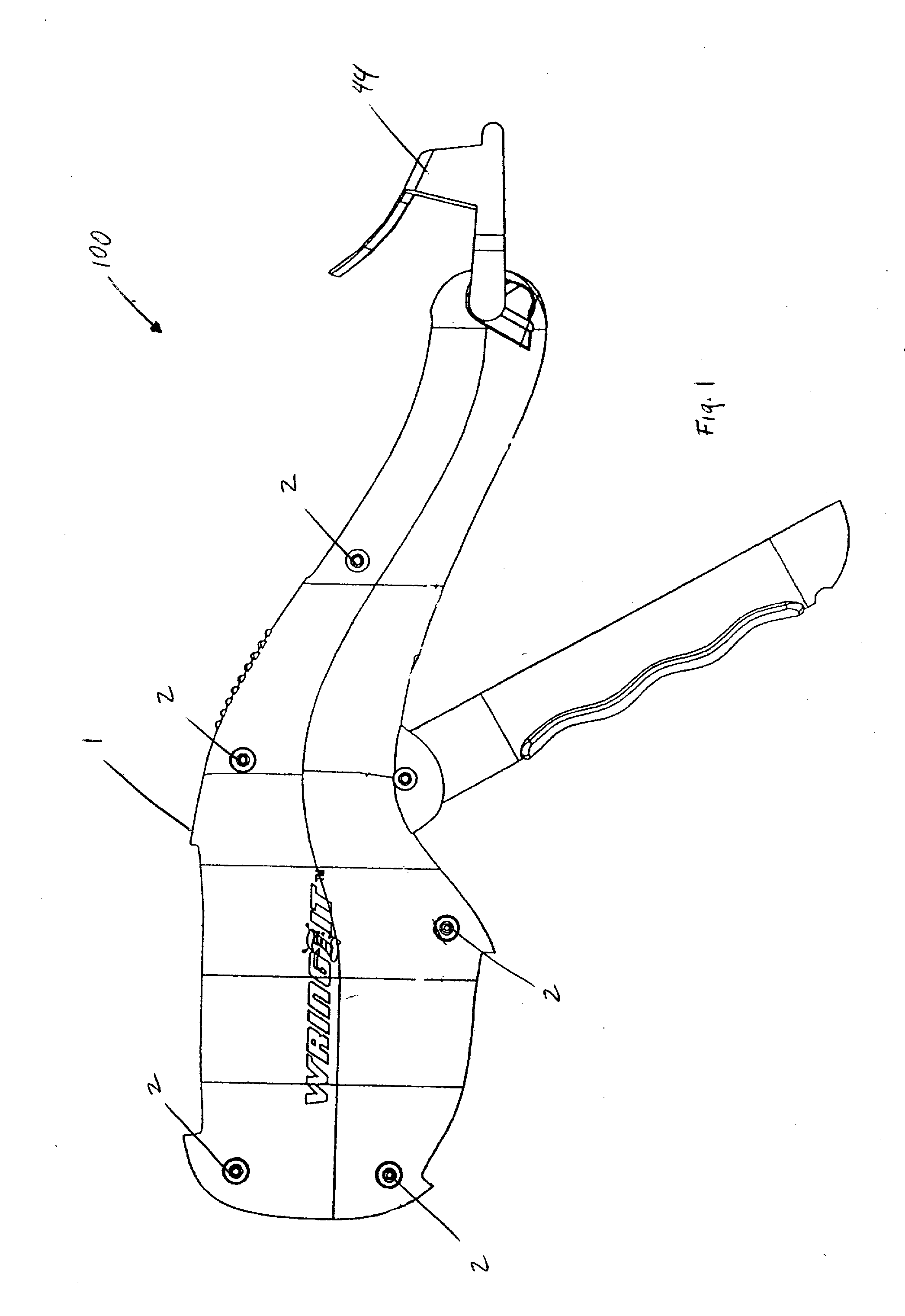
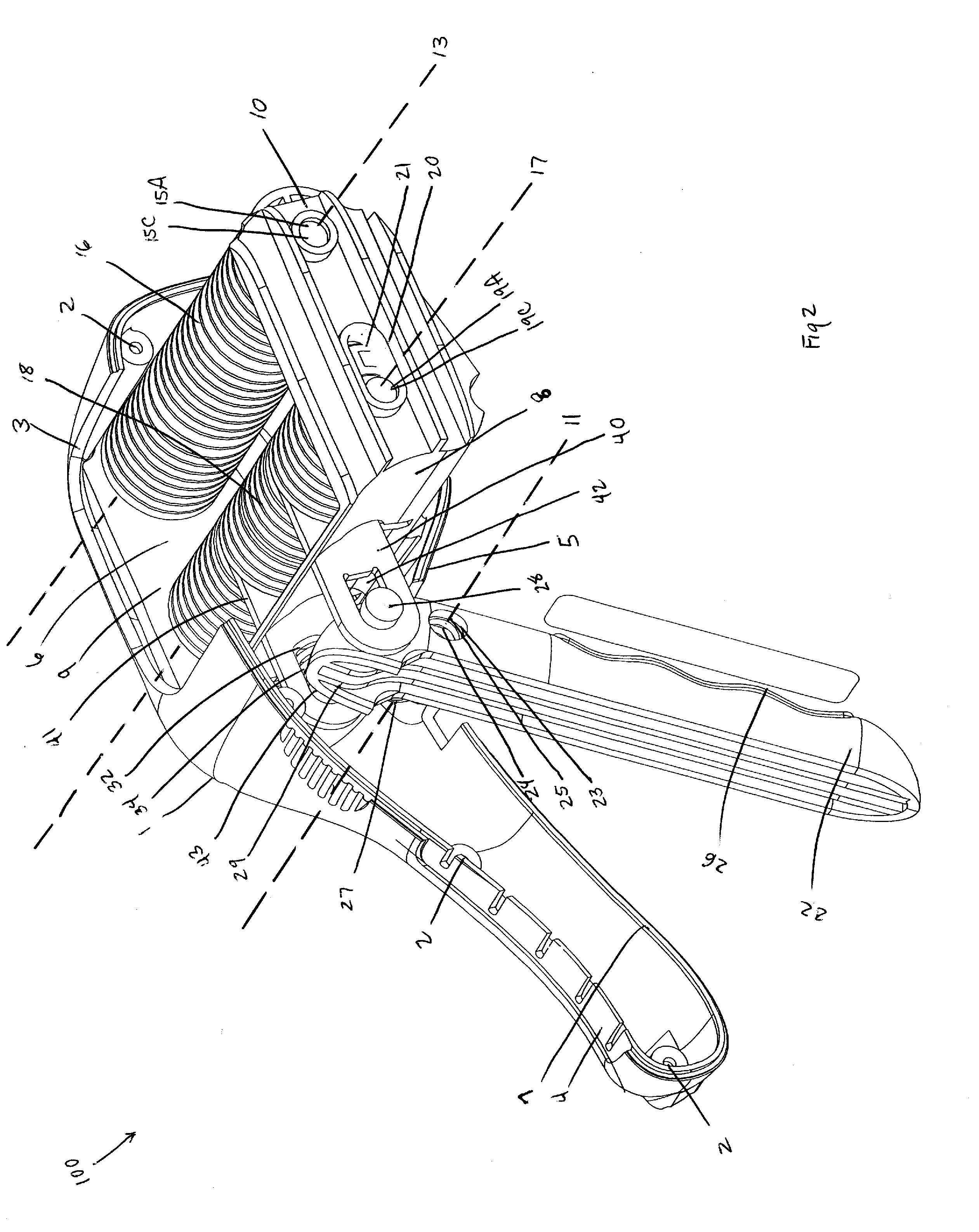
[0028]Referring now to FIGS. 1-6, wherein like elements are numbered consistently throughout, FIGS. 1-3 illustrate the preferred embodiment of the hand-held wringer, generally referenced herein as 100. The hand-held wringer 100 is comprised of a support structure 1. The support structure 1 is constructed of plastic molding, however, composite material, metal, Plexiglas® (acrylic glass or polymethyl methacrylate), or the like are suitable alternatives. The support structur...


PUM


Abstract

The present invention provides a hand-held wringer for removing liquid from a wet or damp material. A wet or damp material is placed between two rollers and a trigger handle is engaged to reduce the space between one roller's axis relative to an opposite roller's axis so as to expel liquid from every fiber of the material as it is pulled therethrough.

Description

CROSS-REFERENCE TO RELATED APPLICATIONS[0001]This non-provisional application claims priority under 35 U.S.C. 119 (a) on U.S. Patent Application No. 60 / 950,248, entitled Hand-Held Wringer, filed Jul. 17, 2007, the entirety of which is incorporated herein by reference.FIELD OF THE INVENTION[0002]This invention relates generally to material wringers, and more particularly, to a hand-held roller type wringer with a spring pressure applying and releasing mechanism for removing liquid from a chamois, cloth, clothing, diaper, hosiery, mop, fabric, towel, undergarments, or like materials.BACKGROUND OF THE INVENTION[0003]Removal of water from land vehicles and water vehicles helps to maintain that shiny new showroom look on a vehicle. Proper maintenance requires drying off the exterior surface of the vehicle to effectively remove water spots that otherwise will remain on the surface of the vehicle. One of the many techniques vehicle owners have employed to dry their vehicles is a reusable c...

Claims


Application Information

Patent Timeline
IPC IPC(8): D06F45/00
CPCD06F45/02
Inventor VARGA, GEORGE
Owner VARGA GEORGE
Why Eureka
Try Eureka