Method of determining the zero-clearance pressure in a controlled clearance piston gauge

a technology of controlled clearance and piston gauge, which is applied in the direction of fluid pressure measurement using pistons, instruments, fluid pressure measurement by mechanical elements, etc., can solve the problem of much too slow sink rate to accurately measure the sink rate, and achieve simple and accurate way, improve the capability of determining the zero clearance pressure, and more sensitive and repeatability

Inactive Publication Date: 2009-01-22
FLUKE ELECTRONICS
View PDF5 Cites 0 Cited by
  • Summary
  • Abstract
  • Description
  • Claims
  • Application Information

AI Technical Summary

Benefits of technology

[0005]The subject invention features a new method of determining the zero clearance pressure in a controlled clearance piston gauge and a new system for implementing the method. The inventive method is substantially more sensitive and repeatable than the prior sink rate measurement method particularly at the very low flow rates that occur when the jacket pressure is close to the zero clearance pressure and the system pressure is near the low end of the operating range. The method provides a simple and accurate way to substantially improve the capability of determining the zero clearance pressure especially for pneumatic controlled clearance piston gauges.

Problems solved by technology

Also, in some cases, particularly for pneumatic piston-cylinder assemblies with highly precise geometries, the sink rates are much too slow to measure the sink rate accurately enough for the purpose of estimating the zero clearance pressure.

Method used


Image

  • Method of determining the zero-clearance pressure in a controlled clearance piston gauge
  • Method of determining the zero-clearance pressure in a controlled clearance piston gauge
  • Method of determining the zero-clearance pressure in a controlled clearance piston gauge

Examples


Embodiment Construction

[0016]Aside from the preferred embodiment or embodiments disclosed below, this invention is capable of other embodiments and of being practiced or being carried out in various ways. Thus, it is to be understood that the invention is not limited in its application to the details of construction and the arrangements of components or steps set forth in the following description or illustrated in the drawings. If only one embodiment is described herein, the claims hereof are not to be limited to that embodiment. Moreover, the claims hereof are not to be read restrictively unless there is clear and convincing evidence manifesting a certain exclusion, restriction, or disclaimer.

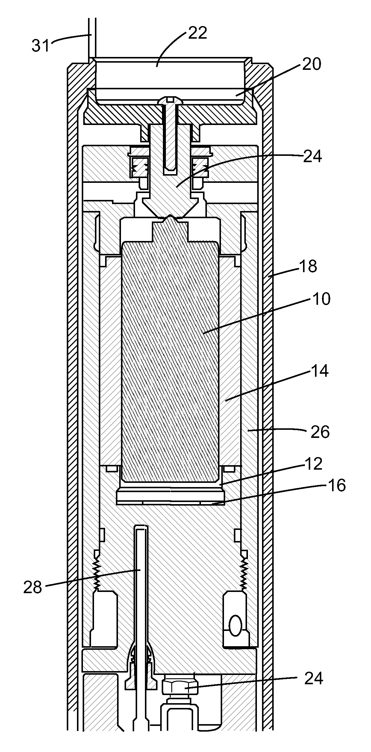
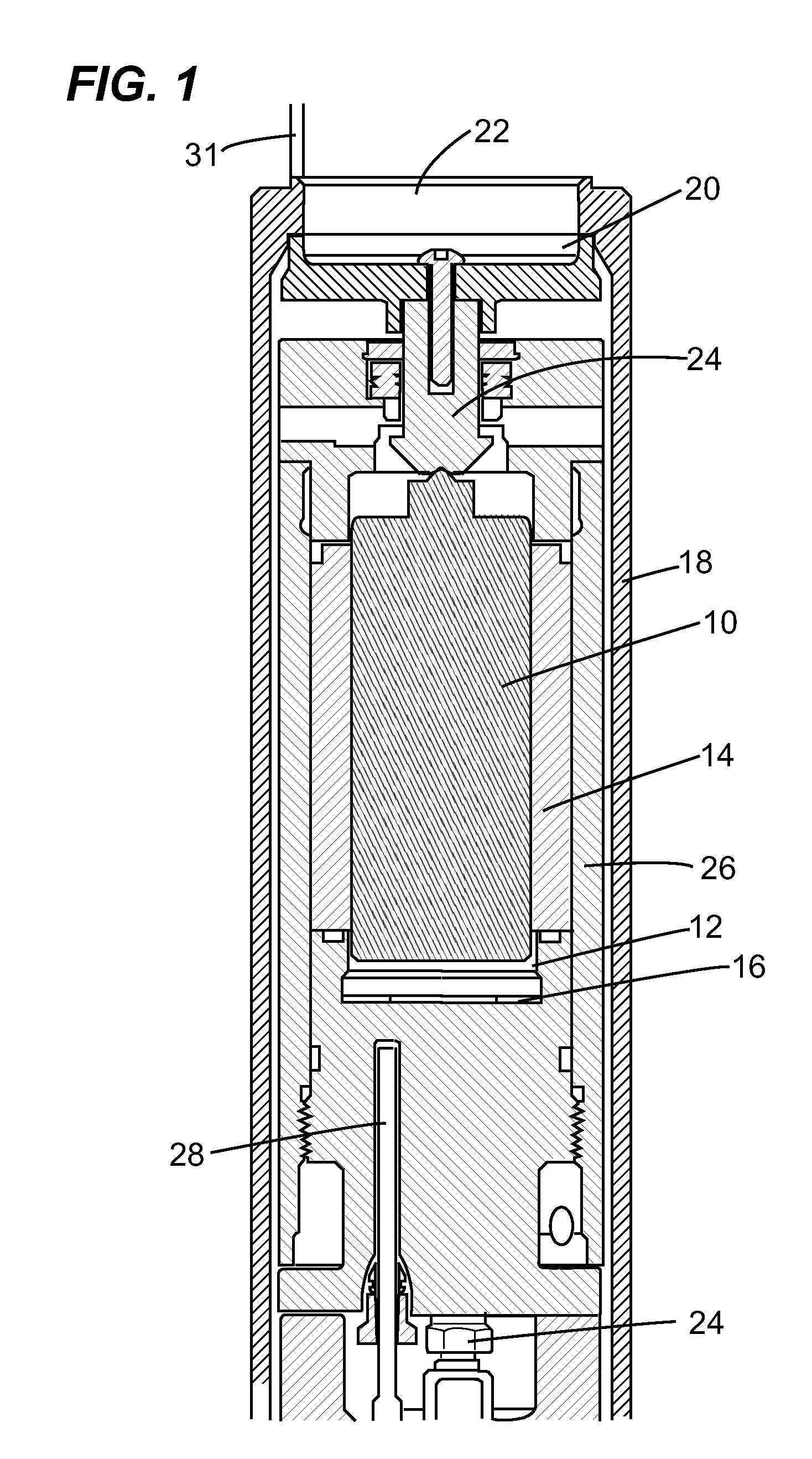
[0017]FIG. 1 shows a typical controlled clearance piston gauge with piston 10 in cylinder 14 surrounded by pressurizable pressure jacket 26. Cushion disk 16 is disposed at the bottom of upper cavity 12 of mounting post 45. The gauge also includes outer sleeve weight 18 and a weight loading assembly including table ...


PUM

PropertyMeasurementUnit
Hydraulic Pressureaaaaaaaaaa
pressureaaaaaaaaaa
clearance pressureaaaaaaaaaa

Abstract

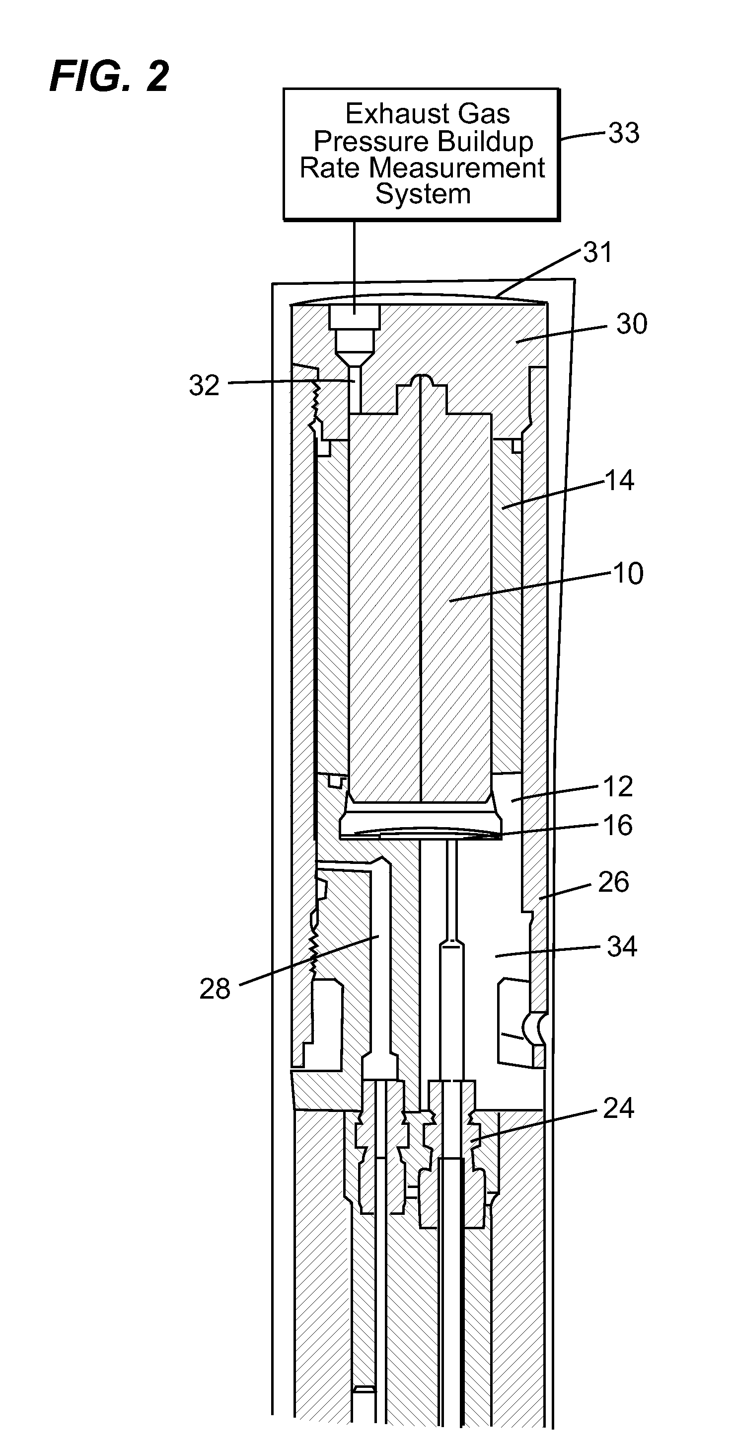
A method of determining the zero clearance pressure in a controlled clearance piston gauge. The typical method includes pressurizing the cylinder in which the piston resides to a given system pressure. The jacket pressure is then changed and the exhaust gas pressure build-up rate at different jacket pressures is measured. The zero clearance pressure to be where the exhaust gas pressure build-up rate is zero.

Description

FIELD OF THE INVENTION[0001]This subject invention relates to controlled clearance piston gauges.BACKGROUND OF THE INVENTION[0002]Controlled clearance piston gauges are used as primary pressure standards. See “Intercomparison of Hydraulic Pressure Measurements to 28 MPa Using a Single-Piston Gauge in the Controlled-Clearance, Reentrant, and Simple Configurations”, K. Jain et al., Rev. Sci. Instum., Vol. 63, No. 5, May 1992, pp. 3127-3135 incorporated herein by this reference. See also “The Controlled-Clearance Principle”, Donald H. Newhall, Industrial and Engineering Chemistry, Vol. 49, No. 12, December 1957, pp. 1993-1995 also incorporated herein by this reference.[0003]A controlled clearance piston gauge includes a piston surrounded by a jacket which can be pressurized to reduce the space between the piston and the cylinder bore until a zero clearance condition is achieved at a jacket pressure called the zero clearance pressure (Pz). The pressure measured by a controlled clearance...

Claims


Application Information

Patent Timeline
Patent Type & Authority Applications(United States)
IPC IPC(8): G01L27/00
CPCG01L27/005
Inventor KOLB, KENNETH A.
Owner FLUKE ELECTRONICS
Why Eureka
Try Eureka