Flat panel crystal display employing simultaneous charging of main and subsidiary pixel electrodes

a technology of pixel electrodes and crystal displays, which is applied in the field of flat panel displays, can solve the problems of difficult to suitably provide sufficient charging time of each independent electrode inside the pixel unit, and the viewing angle is relatively narrow, and achieves the effects of low power consumption, large screen sizes, and high resolution

Active Publication Date: 2009-01-22
SAMSUNG DISPLAY CO LTD
View PDF8 Cites 28 Cited by
  • Summary
  • Abstract
  • Description
  • Claims
  • Application Information

AI Technical Summary

Benefits of technology

[0005]A liquid crystal display (LCD), which is one of a variety of different kinds of flat panel displays, is a device that forms an image by adjusting a transmitted amount of light supplied from a light source by using the optical anisotropy property of liquid crystal molecules and the polarization characteristics of a polarizer to control light transmitivity through each of color-filter covered pixel units. The process of controlling the orientation of the liquid crystal molecules includes charging one or more electrodes (pixel-electrodes) to a desired electrical potential. In recent years, use of liquid crystal displays has been increasingly widening because it has various features such as being lightweight, compact, offering high resolution, large screen sizes, and low power consumption.
[0006]However the conventional liquid crystal display (e.g., the kind with just one pixel-electrode per pixel unit) suffers from the drawback of having a relatively narrower viewing angle than that of other kinds of displays because it forms an image by using the light transmitted only along a main transmission axis of liquid crystal molecules in a main area of each pixel unit. Thus, in order to widen

Problems solved by technology

However the conventional liquid crystal display (e.g., the kind with just one pixel-electrode per pixel unit) suffers from the drawback of having a relatively narrower viewing angle than that of other kinds of displays because it forms an image by using the light transmitted only along a main transmission axis of liquid crystal molecules in a main area of each pixel unit.
However, when compared to the more conventional 1G-1D cell structure, the SPVA scheme suffers the drawback that it has more independent pixel-electrodes in need of in

Method used


Image

  • Flat panel crystal display employing simultaneous charging of main and subsidiary pixel electrodes
  • Flat panel crystal display employing simultaneous charging of main and subsidiary pixel electrodes
  • Flat panel crystal display employing simultaneous charging of main and subsidiary pixel electrodes

Examples


second embodiment

[0052]The present disclosure is not limited to the above first description. In an alternate embodiment, a plurality of gate drivers may be provided at both sides of the liquid crystal display panel 700 (FIG. 4) to apply gate signals to the gate lines. The liquid crystal display according to a second embodiment will now be described. In this case, a description of the same features as in the first embodiment will be omitted or briefly described.

[0053]FIG. 4 is a block diagram illustrating a liquid crystal display according to a second embodiment.

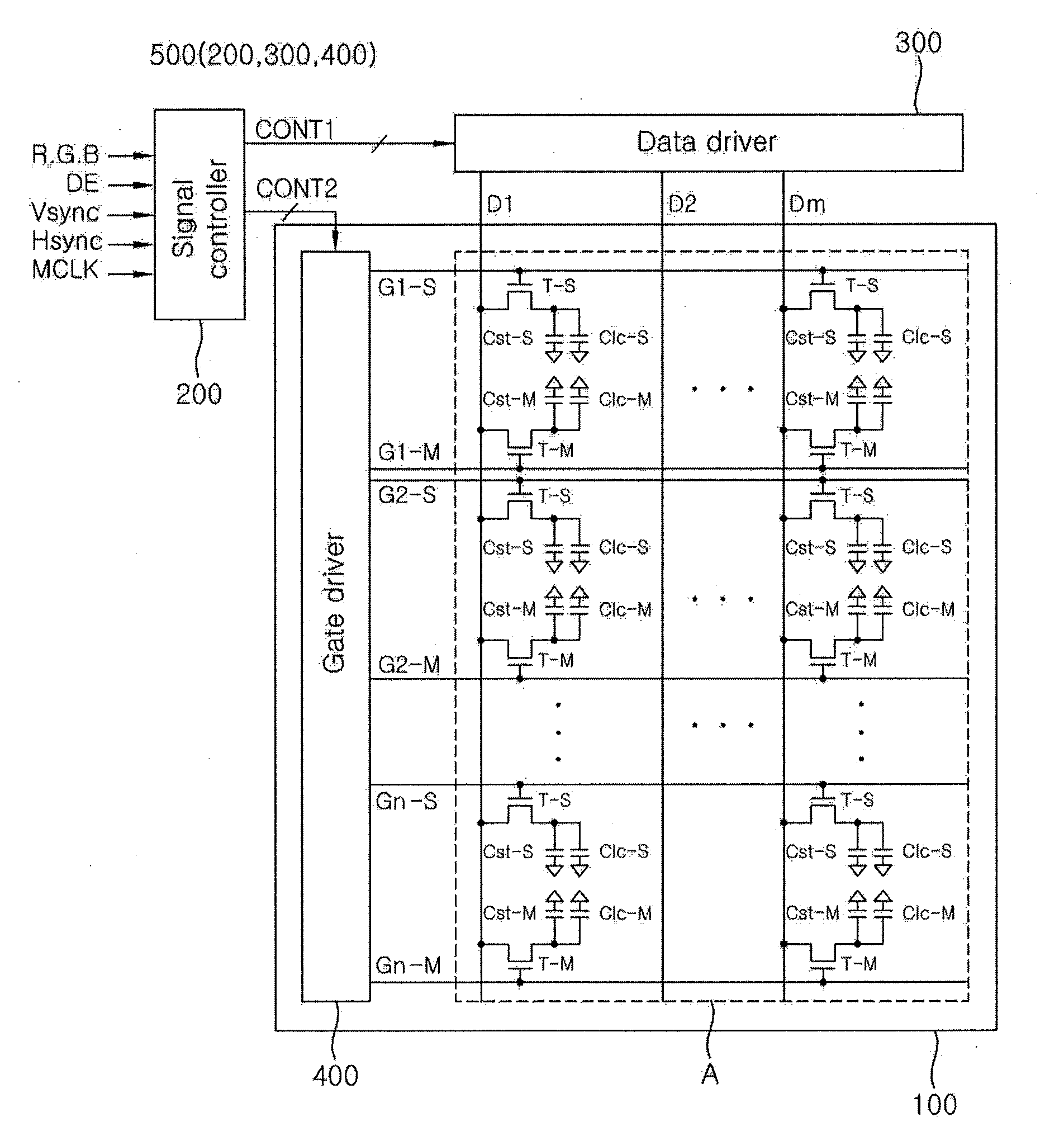
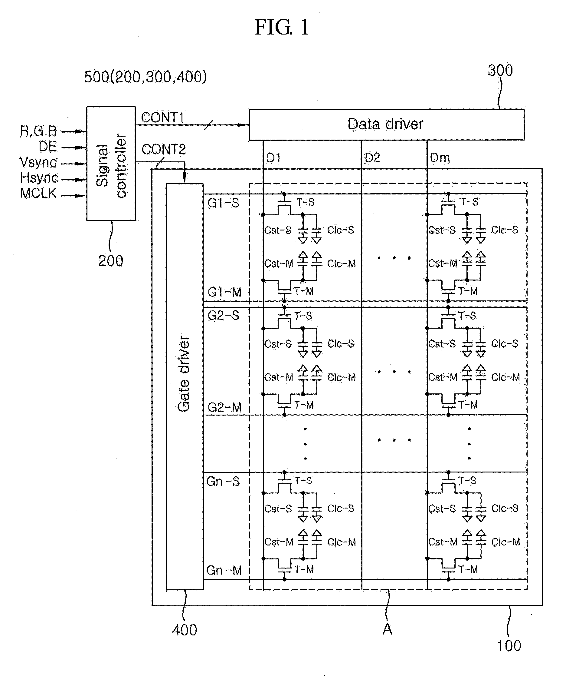
[0054]Referring to FIG. 4, the liquid crystal display according to this embodiment includes a liquid crystal display panel 700 having a plurality of pixels arranged in a matrix form in a display area A, and a liquid crystal driving circuit 900 for controlling operation of the pixels. The liquid crystal driving circuit 900 includes a signal controller 200, a data driver 300, and first and second gate drivers 810 and 820. The liquid crystal dri...


PUM


Abstract

A display system includes a display panel having a plurality of pixel units, each of the pixel units having first and second divided pixel parts; a first driver for applying a first gate signal to the first divided pixel part; and a second driver for applying a second gate signal to the second divided pixel part, wherein the first and second drivers are integrally formed in the display panel and apply the first and second gate signals to be at least partially time-overlapped through independent driving.

Description

[0001]This application claims priority to and the benefit of Korean Patent Application No. 10-2007-0072997 filed on Jul. 20, 2007, whose disclosure is hereby incorporated by reference for all purposes as if fully set forth herein.BACKGROUND[0002]1. Field of Invention[0003]The present disclosure of invention relates to flat panel displays, and more particularly, to liquid crystal displays (LCD's) in which each pixel unit is divided into a main pixel area and a subsidiary pixel area and the pixel-electrodes of these divided areas are to be charged to different potentials during a same horizontal line period.[0004]2. Description of the Related Art[0005]A liquid crystal display (LCD), which is one of a variety of different kinds of flat panel displays, is a device that forms an image by adjusting a transmitted amount of light supplied from a light source by using the optical anisotropy property of liquid crystal molecules and the polarization characteristics of a polarizer to control li...

Claims


Application Information

Patent Timeline
IPC IPC(8): G09G5/00
CPCG09G3/3677G09G2300/0408G09G2310/0205G09G2300/0447G09G2300/0443G09G3/36G02F1/133G02F1/1345G09G3/20
Inventor LEE, MIN-CHEOLMOON, SEUNG-HWAN
Owner SAMSUNG DISPLAY CO LTD
Why Eureka
Try Eureka