Power transmission control device, power transmission device, electronic instrument, and non-contact power transmission system

a technology of power transmission control and control device, which is applied in the direction of safety/protection circuit, transportation and packaging, inductance, etc., can solve the problem that the accuracy of foreign objects cannot be improved to a satisfactory level

Active Publication Date: 2009-01-29
CHAMIRAUX MANAGEMENT LLC
View PDF3 Cites 74 Cited by
  • Summary
  • Abstract
  • Description
  • Claims
  • Application Information

AI Technical Summary

Benefits of technology

[0020]a driver control circuit that generates a driver control signal based on the drive clock signal, and outputs the driver control signal to a transmission driver that drives the primary coil;

Problems solved by technology

Therefore, the foreign object detection accuracy cannot be improved to a satisfactory level.

Method used


Image

  • Power transmission control device, power transmission device, electronic instrument, and non-contact power transmission system
  • Power transmission control device, power transmission device, electronic instrument, and non-contact power transmission system
  • Power transmission control device, power transmission device, electronic instrument, and non-contact power transmission system

Examples


Embodiment Construction

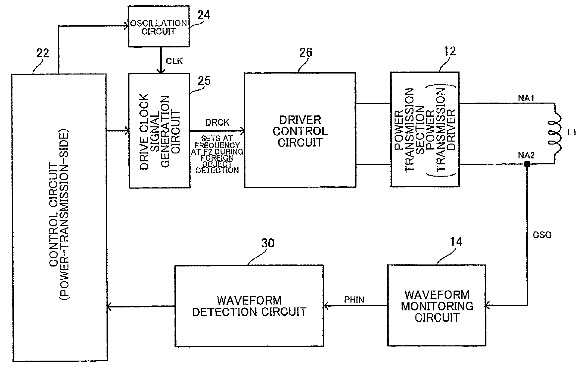
[0042]Several aspects of the invention may provide a power transmission control device, a power transmission device, an electronic instrument, and a non-contact power transmission system capable of improving the foreign object detection accuracy.

[0043]According to one embodiment of the invention, there is provided a power transmission control device provided in a power transmission device included in a non-contact power transmission system, the non-contact power transmission system transmitting power from the power transmission device to a power reception device by electromagnetically coupling a primary coil and a secondary coil to transmit the power to a load of the power reception device, the power transmission control device comprising:[0044]a drive clock signal generation circuit that generates a drive clock signal that specifies a drive frequency of the primary coil;

[0045]a driver control circuit that generates and outputs a driver control signal based on the drive clock signal...


PUM

PropertyMeasurementUnit
voltageaaaaaaaaaa
threshold voltage VT1aaaaaaaaaa
low-potential-side threshold voltage VTLaaaaaaaaaa

Abstract

A power transmission control device provided in a power transmission device of a non-contact power transmission system includes a drive clock signal generation circuit that generates a drive clock signal specifying a drive frequency of a primary coil, a driver control circuit that generates a driver control signal based on the drive clock signal, and outputs the driver control signal to a transmission driver, a waveform detection circuit that detects a change in waveform of an induced voltage signal of the primary coil, and a control circuit that performs foreign object detection based on a detection result of the waveform detection circuit. The drive clock signal generation circuit outputs the drive clock signal set at a foreign object detection frequency during foreign object detection, the foreign object detection frequency being a frequency differing from a normal power transmission frequency.

Description

[0001]Japanese Patent Application No. 2007-171346 filed on Jun. 29, 2007 and Japanese Patent Application No. 2007-184270 filed on Jul. 13, 2007, are hereby incorporated by reference in their entirety.BACKGROUND OF THE INVENTION[0002]The present invention relates to a power transmission control device, a power transmission device, an electronic instrument, a non-contact power transmission system, and the like.[0003]In recent years, non-contact power transmission (contactless power transmission) that utilizes electromagnetic induction to enable power transmission without metal-to-metal contact has attracted attention. As application examples of non-contact power transmission, charging a portable telephone, charring a household appliance (e.g., cordless telephone handset), and the like have been proposed.[0004]JP-A-2006-60909 discloses related-art non-contact power transmission. According to the technology disclosed in JP-A-2006-60909, a power transmission device (primary-side instrume...

Claims


Application Information

Patent Timeline
Patent Type & Authority Applications(United States)
IPC IPC(8): H01F38/00
CPCH02J7/025H01F38/14H02J50/10H02J7/00045H02J7/00304H02J50/12H02J50/80H02J50/90H02J50/60
Inventor IISAKA, KENJIN, MIKIMOTO
Owner CHAMIRAUX MANAGEMENT LLC
Why Eureka
Try Eureka