
Method and Apparatus for Charging Batteries

a battery and charging method technology, applied in the field of battery chargers, can solve the problems of long charging time of inability to perform fast charge type lithium ion rechargeable batteries to its full capacity, and 75 minutes of fast charge type lithium ion rechargeable batteries to be charged to the same capacity

Active Publication Date: 2009-01-29
LENOVO PC INT
View PDF6 Cites 70 Cited by
  • Summary
  • Abstract
  • Description
  • Claims
  • Application Information

AI Technical Summary

Benefits of technology

[0003]The present invention relates to battery chargers in general, and in particular to a method for reducing charging time of a battery having a charging rate greater than the capacity of a battery charger.

Problems solved by technology

Although lithium ion rechargeable batteries have high energy density, the charging time of lithium ion rechargeable batteries tend to be long.
When a fast charge type lithium ion rechargeable battery is charged by a battery charger having a capacity capable of charging normal charge type lithium ion rechargeable batteries, the fast charge type lithium ion rechargeable battery cannot perform up to its full capability because of the insufficient charging capacity.
However, when the fast charge type lithium ion rechargeable battery is charged by a battery charger adapted for normal charge type lithium ion rechargeable batteries, the fast charge type lithium ion rechargeable battery may take 75 minutes to be charged to the same capacity.
However, when the capacity of a battery charger mounted within a notebook PC is increased in order to be able to handle the fast charge type lithium ion rechargeable battery, the battery charger becomes bulky, which may cause problems such as reducing inner space of the notebook PC, increasing heat generation and increasing cost.

Method used


Image

  • Method and Apparatus for Charging Batteries
  • Method and Apparatus for Charging Batteries
  • Method and Apparatus for Charging Batteries

Examples


Embodiment Construction

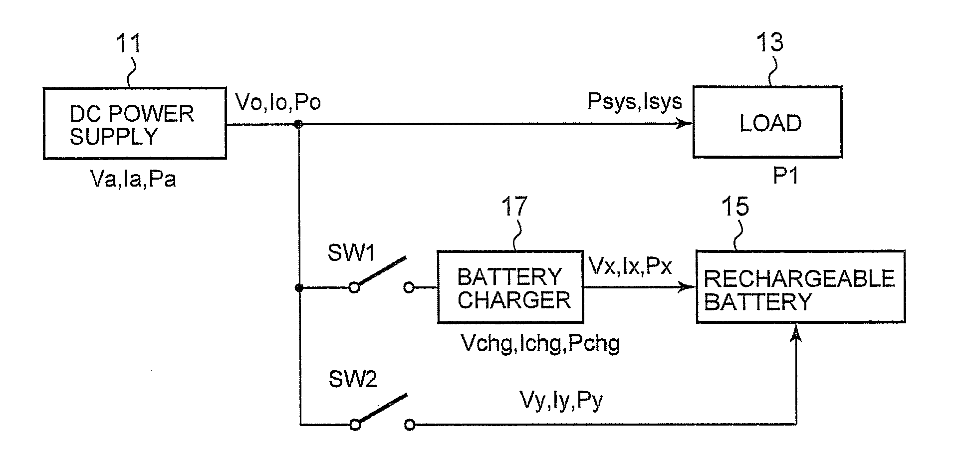
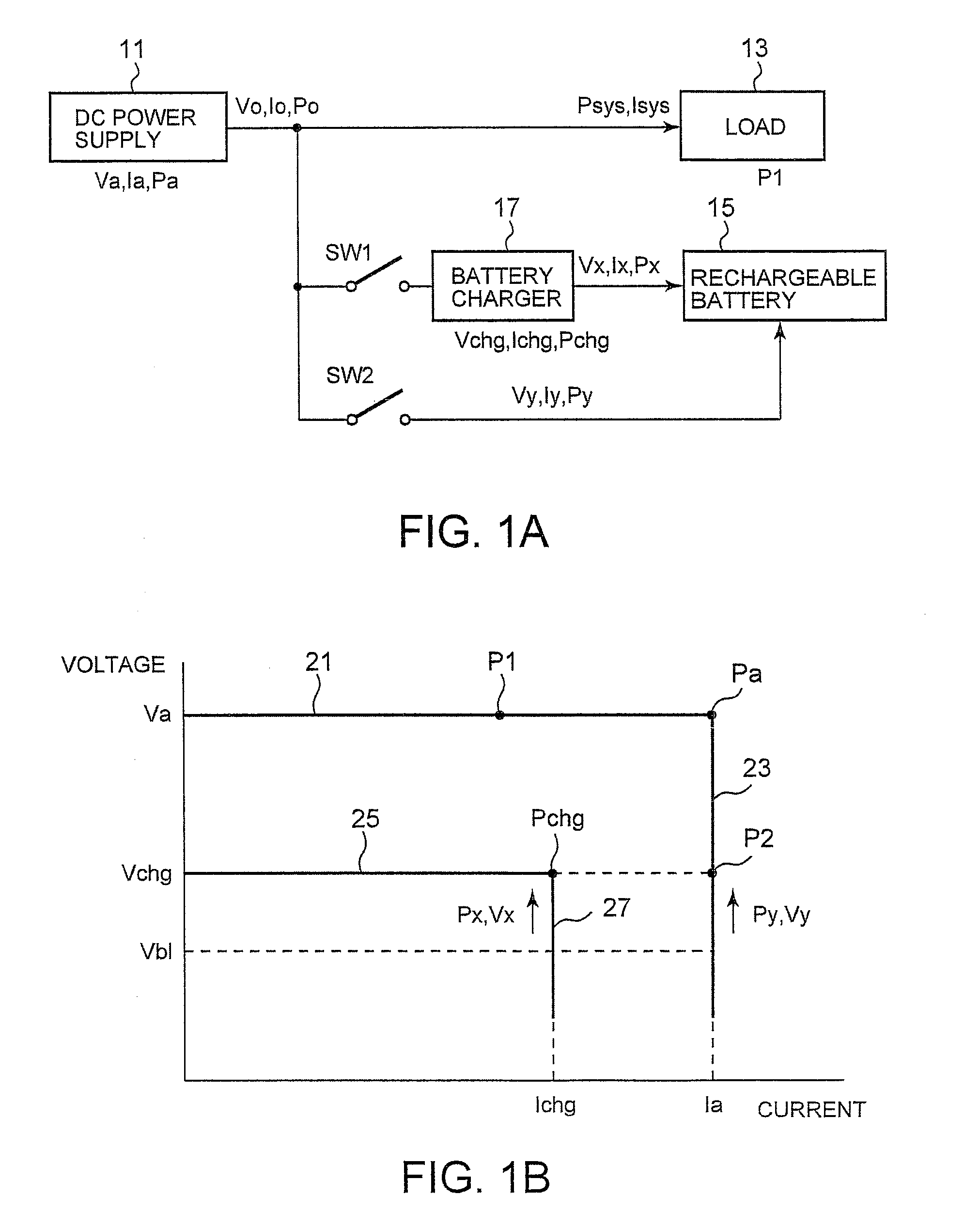
[0016]FIG. 1A is a block diagram illustrating a basic construction of a battery charging system, according to an embodiment of the present invention. The battery charging system has two charging modes: a first charging mode wherein charging is performed by means of a battery charger 17 and a second charging mode wherein charging is performed by means of a DC power supply 11. In FIG. 1A, the DC power supply 11 is a voltage converter that converts an AC voltage or a DC voltage into a predetermined DC voltage. The DC power supply 11 is able to supply electric power to the battery charger 17 by opening a switch SW2 and closing a switch SW1 while supplying electric power to a system load 13. The DC power supply 11 is also able to directly charge the rechargeable battery 15 by opening the switch SW1 and closing the switch SW2 while supplying electric power to the system load 13.

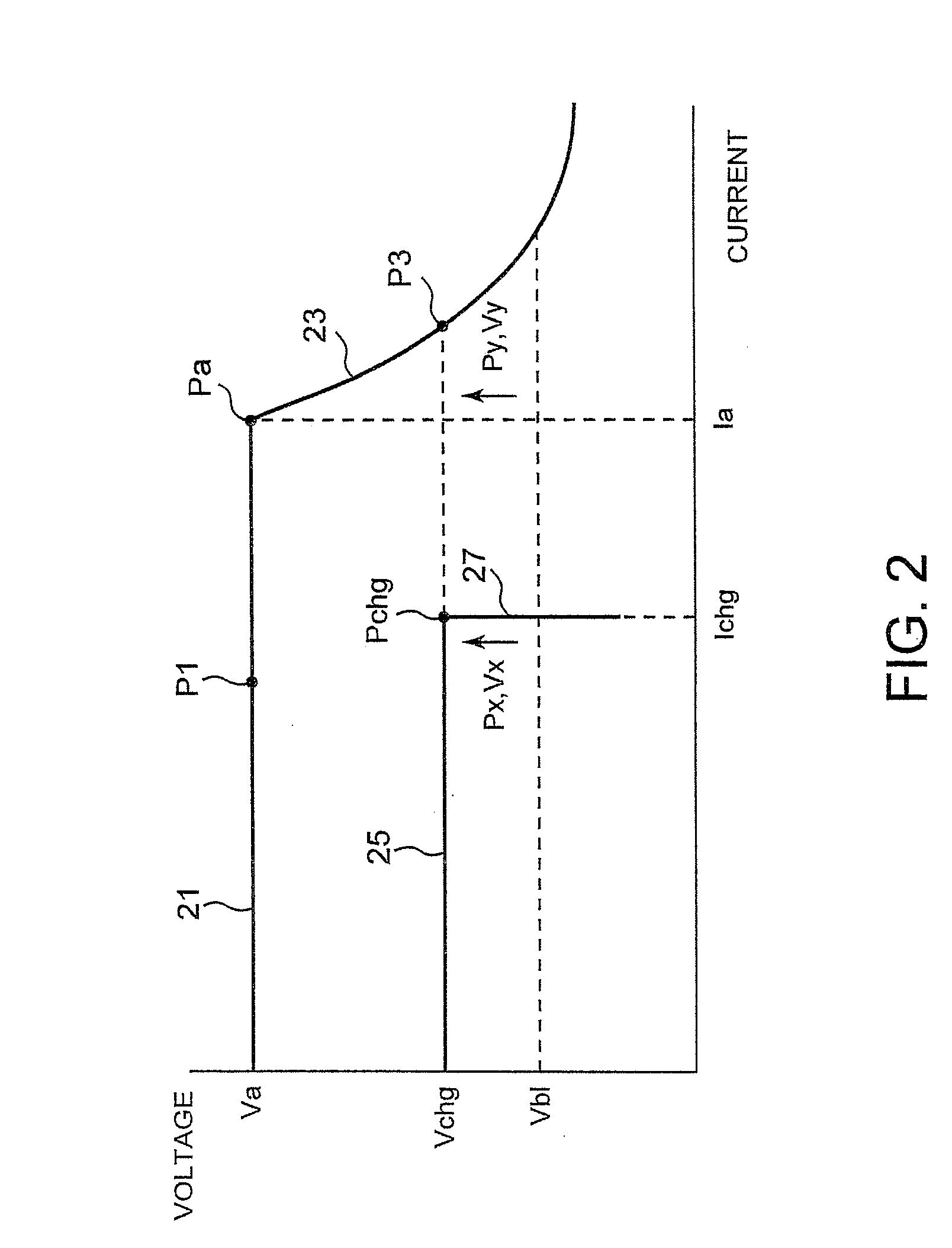
[0017]FIG. 1B is a chart illustrating the voltage-current characteristics of a battery charger 17 and a DC power...


PUM


Abstract

A battery charging system is disclosed. The battery charging system includes a battery charger, a switching circuit and a control circuit. The battery charger receives electric power from a DC power supply and charges a rechargeable battery based on a setting current. The switching circuit is capable of switching between a first charging mode and a second charging mode. In the first charging mode, the battery charger charges the rechargeable battery while the DC power supply is supplying electric power to the battery charger in a state where the DC power supply is able to supply electric power to a load. In the second charging mode, the DC power supply charges the rechargeable battery in a state where the DC power supply is able to supply electric power to the load. The control circuit controls the switching circuit based on a comparison result of the magnitude of a charging current (or a charging power) in the first charging mode and the magnitude of a charging current (or a charging power) in the second charging mode.

Description

PRIORITY CLAIM[0001]The present application claims benefit of priority under 35 U.S.C. §§ 120, 365 to the previously filed Japanese Patent Application No. JP2007-195648 entitled, “Charging System and Charging Method” with a priority date of Jul. 27, 2007, which is incorporated by reference herein.BACKGROUND OF THE INVENTION[0002]1. Technical Field[0003]The present invention relates to battery chargers in general, and in particular to a method for reducing charging time of a battery having a charging rate greater than the capacity of a battery charger.[0004]2. Description of Related Art[0005]Lithium ion rechargeable batteries can be found in many portable electronic devices such as notebook personal computers (PCs). Although lithium ion rechargeable batteries have high energy density, the charging time of lithium ion rechargeable batteries tend to be long. In recent years, a fast charge type lithium ion rechargeable battery that employs nano-sized particles as negative-electrode mate...

Claims


Application Information

Patent Timeline
Patent Type & Authority Applications(United States)
IPC IPC(8): H02J7/00
CPCH02J7/0068
Inventor ODAOHHARA, SHIGEFUMI
Owner LENOVO PC INT
Features
  • Generate Ideas
  • Intellectual Property
  • Life Sciences
  • Materials
  • Tech Scout
  • Unparalleled Data Quality
  • Higher Quality Content
  • 60% Fewer Hallucinations
Learn More