
Image forming apparatus

Active Publication Date: 2009-01-29
CANON KK
View PDF14 Cites 38 Cited by
  • Summary
  • Abstract
  • Description
  • Claims
  • Application Information

AI Technical Summary

Benefits of technology

[0010]It is a principal object of the present invention to provide an image forming apparatuses which can accomplish the both of downsizing and simplification of the main assembly of the image forming apparatus and the improvement of the operativity with respect to the process cartridge exchange.

Problems solved by technology

The rotation shaft of then and the cover must be obliquely provided relative to the main assembly of the image forming apparatus, and therefore, the operativity is poor.
When it does so, then, the distances between the rotation shafts of the cover and the cartridge supporting members differ from each other, with the result that, the linkages become complicated and bulky, and therefore, the downsizing of the device will not be accomplished.
Therefore, only by combining the prior art simply, both of the improvement of the operativity and downsizing and simplification of device cannot be accomplished.

Method used


Image

  • Image forming apparatus
  • Image forming apparatus
  • Image forming apparatus

Examples


embodiment 1

>

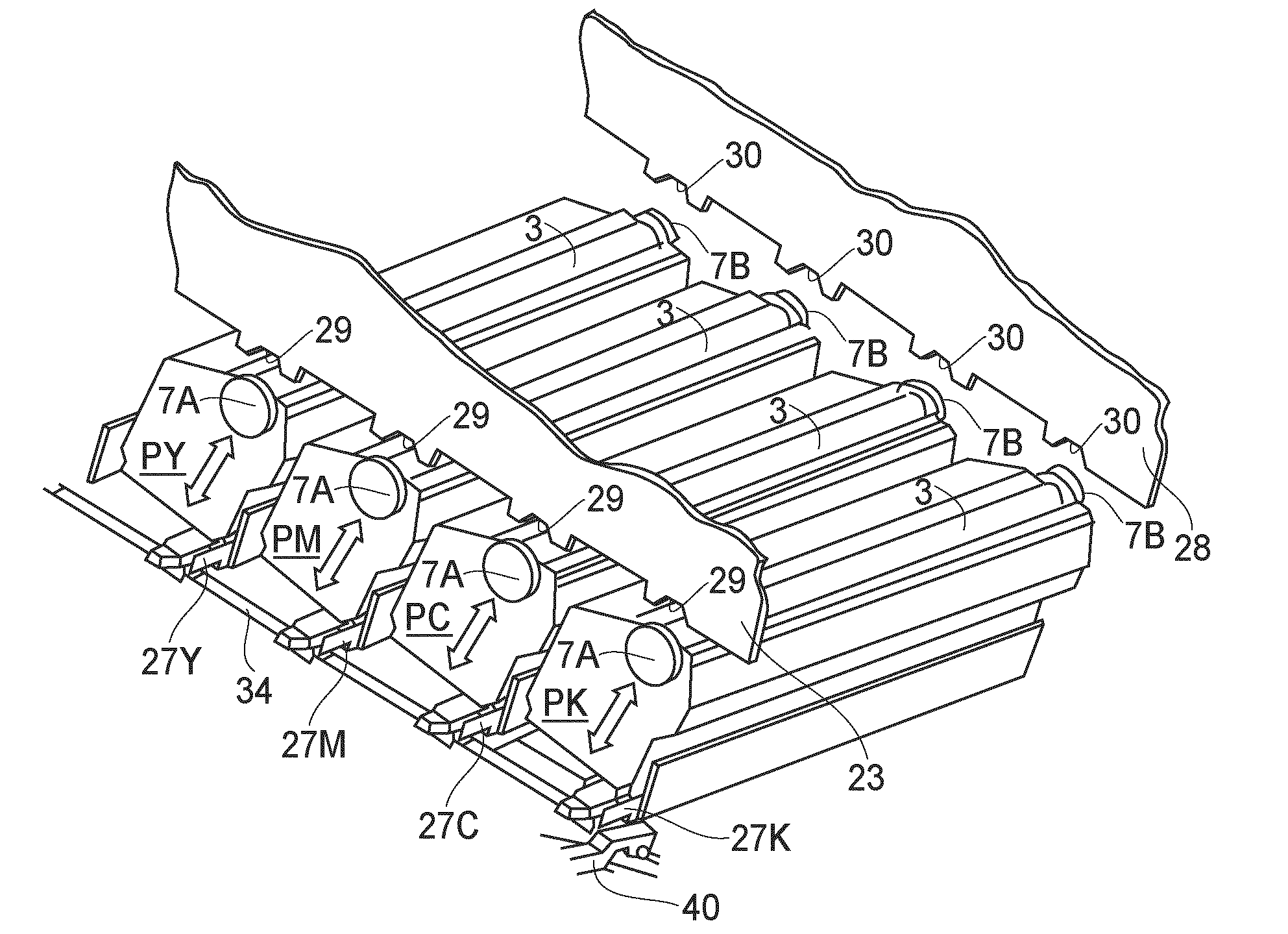
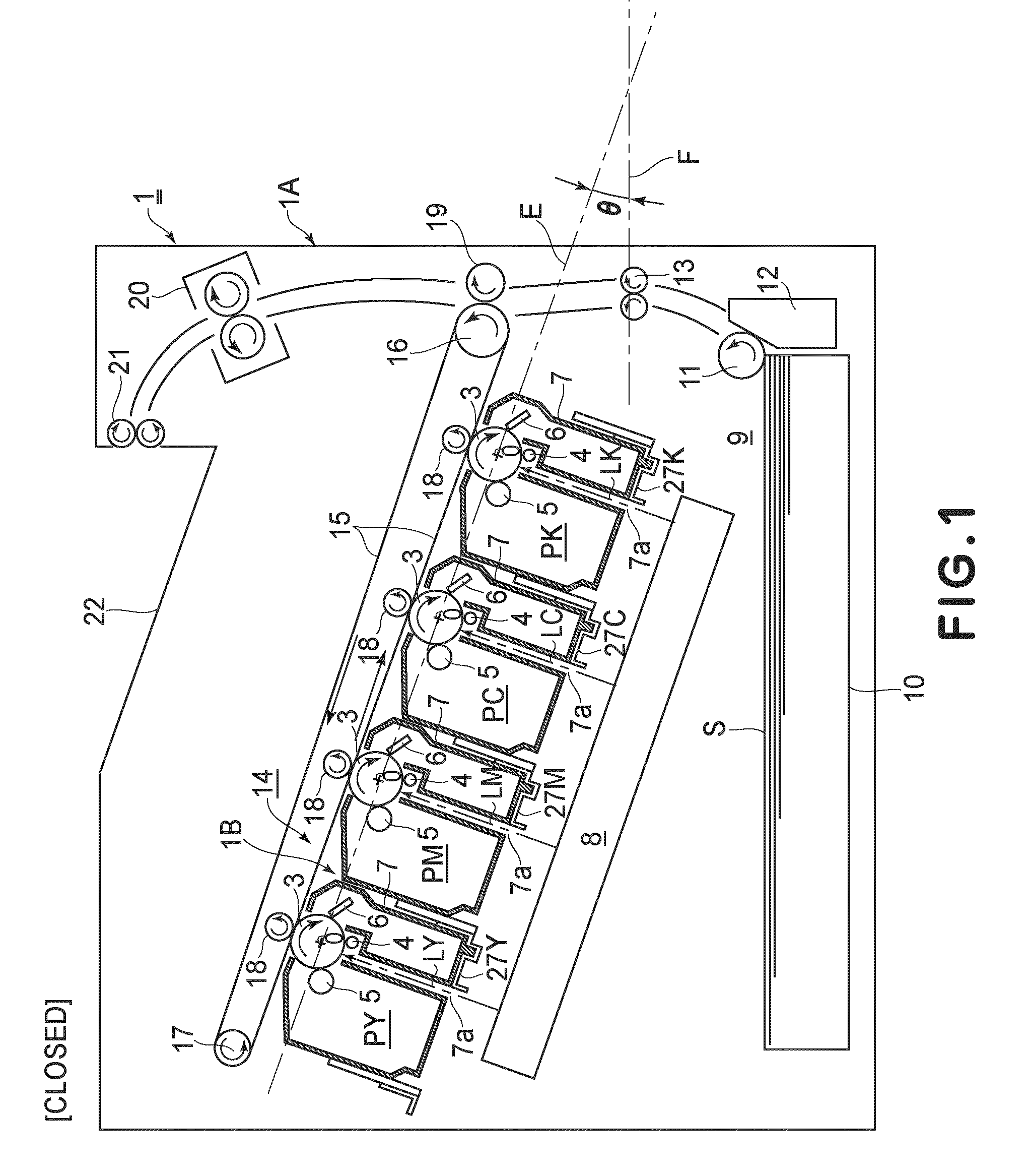
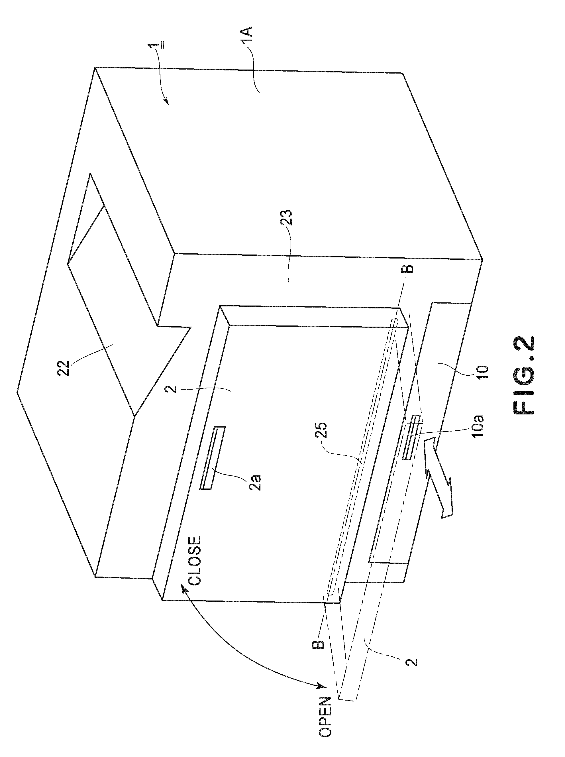
[0033]FIG. 1 is a schematic longitudinal sectional view of an image forming apparatus 1 of the present embodiment. FIG. 2 is an outer appearance perspective view of the image forming apparatus 1 in the state where a front door (exterior cover) 2 is closed. FIG. 3 is an outer appearance perspective view of the image forming apparatus 1 in which the front door 2 is opened wherein, a first process cartridge PY is pulled out halfway.

[0034]This image forming apparatus 1 is a full-color laser beam printer (four colors) which uses an electrophotographic process, and forms the color image on the recording material. This image forming apparatus 1 is the process cartridge mounting and dismounting type in which the first-fourth process cartridges P (PY, PM, PC, PK) are mountable and dismountable relative to the main assembly of the image forming apparatus 1A.

[0035]This image forming apparatus 1 is a full-color laser beam printer (four colors) which uses the electrophotographic process, and fo...

embodiment 2

[0083]FIG. 13 is a schematic perspective view of an image forming apparatus 1 according to the second embodiment. FIG. 14 is a partial enlarged view of FIG. 13, and FIG. 15 (a) is a partial enlarged view of FIG. 14. In the description of this embodiment, the same reference numerals as in Embodiment 1 are assigned to the elements having the corresponding functions in this embodiment, and the detailed description thereof is omitted for simplicity.

[0084]In the image forming apparatus 1, when the front door 2 which is the opening and closing member positions at the open position, the front door 2 is extended toward the outside of the main assembly of the image forming apparatus 1A beyond the opening 24. It is provided with an extension guiding member 42 which is the supporting member for carrying at least a part of cartridge P, and guiding it to the inside of the main assembly of the image forming apparatus 1A at the time of mounting and demounting the cartridge P. This extension guidin...

embodiment 3

[0093]FIG. 16 is an illustration of the image forming apparatus according to a third embodiment. In the description of this embodiment, the same reference numerals as in Embodiments 1 and 2 are assigned to the elements having the corresponding functions in this embodiment, and the detailed description thereof is omitted for simplicity. Designated by 43 is an inner door which is a supporting member disposed inside of the front door 2. This inner door 43 can make the opening and closing rotation relative to the opening 24 of the apparatus main assembly 1 about the rotation shaft 44 which is in parallel with the connecting shaft 34. In the course of the closing operation of the inner door 43, the first link arm 40A integrally rotated with the connecting shaft 34 engages with the second link arm 40B of the inner door 43, and, it rotates the supporting member connecting shaft 34 in interrelation with the closing operation of the inner door 43.

[0094](a) of FIG. 16 shows the state where th...


PUM


Abstract

An image forming apparatus forms an image on a recording material, and detachably mounts which process cartridges having photosensitive drums. The apparatus includes a main assembly, a rotatable openable member, a belt receiving an image or carrying the recording material, supporting members supporting the process cartridges at different levels and movable between drum-contacting and retracted positions, and a connecting member moving the supporting member when the openable member moves to position the supporting member at the drum-contacting position when the openable member is closed, and position the supporting member at the retracted position when the openable member is opened, and including a shaft whose axis crosses the openable member rotational axis, first connecting portions rotatably connected with respective supporting members, and a second connecting portion engaging the openable member and fixed to the shaft closer to the openable member than the first connecting portions are fixed to the shaft.

Description

FIELD OF THE INVENTION AND RELATED ART[0001]The present invention relates to an image forming apparatuses, such as a copying machine, a printer, and a facsimile machine. More particularly, it relates to the image forming apparatus of a type of mounting, demounting and exchanging a process cartridge provided inside a device, with opening and closing the cover of an outer casing.[0002]In a known image forming apparatus, an image bearing member with which a toner image is formed, and image formation device are in the form of a process cartridge detachably mountable to a main assembly of the image forming apparatus, and, therefore, the operations of inspection and the exchanges of the image bearing member and the image formation device are easy.[0003]In a color image forming apparatus which has a plurality of process cartridges disclosed in JP 2004-212986A, the width of the main assembly of the image forming apparatus with respect to the horizontal direction is decreased by arranging th...

Claims


Application Information

Patent Timeline
IPC IPC(8): G03G21/16
CPCG03G21/185G03G2221/1884G03G2221/169G03G2221/1654G03G21/1609G03G21/1814
Inventor MIZUNO, TATSUBUMIMUTO, KAZUFUMI
Owner CANON KK
Learn More