

Automobile accelerator and brake pedal device
- Summary
- Abstract
- Description
- Claims
- Application Information
AI Technical Summary
Benefits of technology
Problems solved by technology
Method used
Image

Examples
Embodiment Construction
[0022]Referring to drawings, an automobile accelerator and brake pedal device of the present invention is described below.
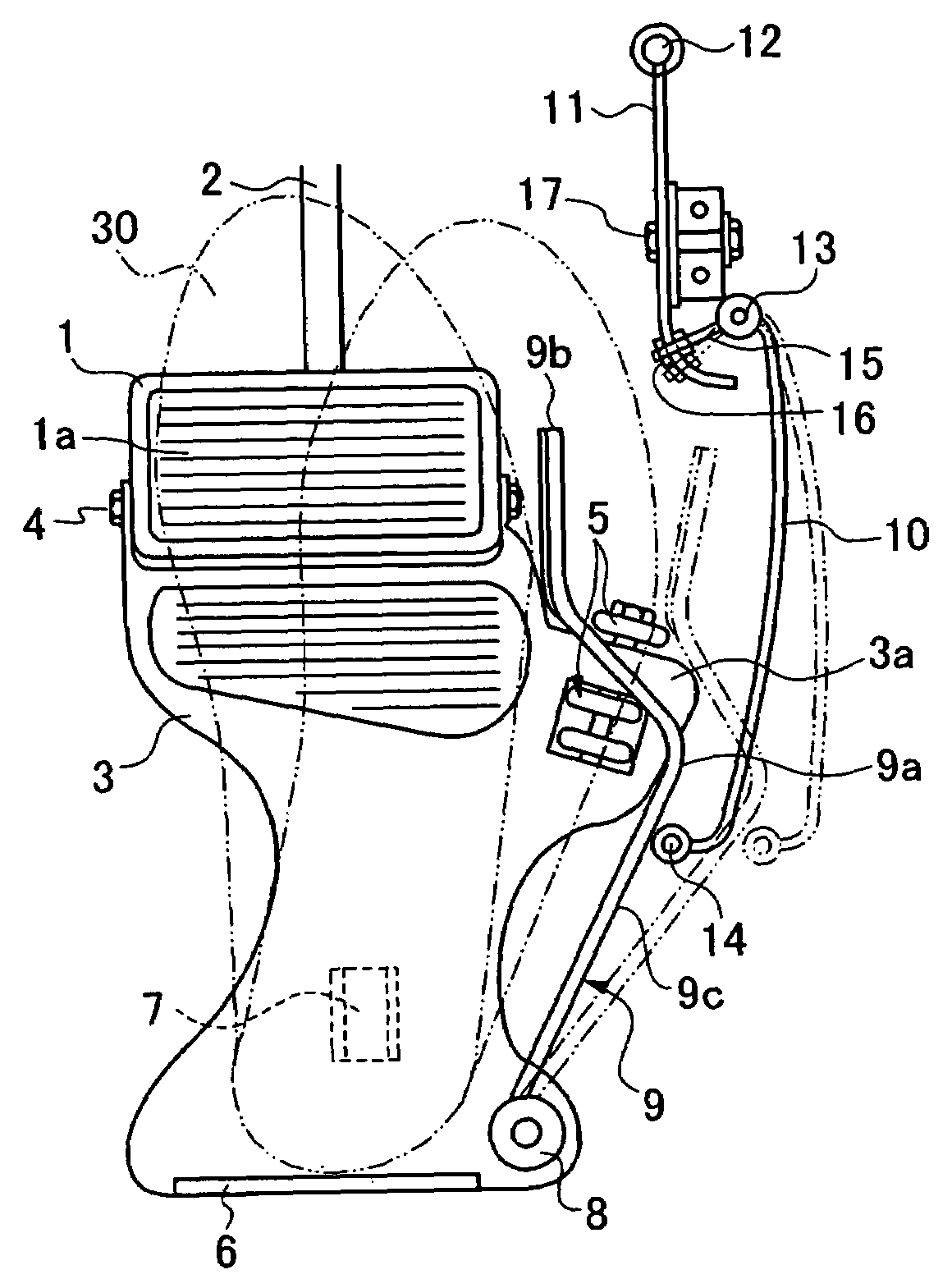
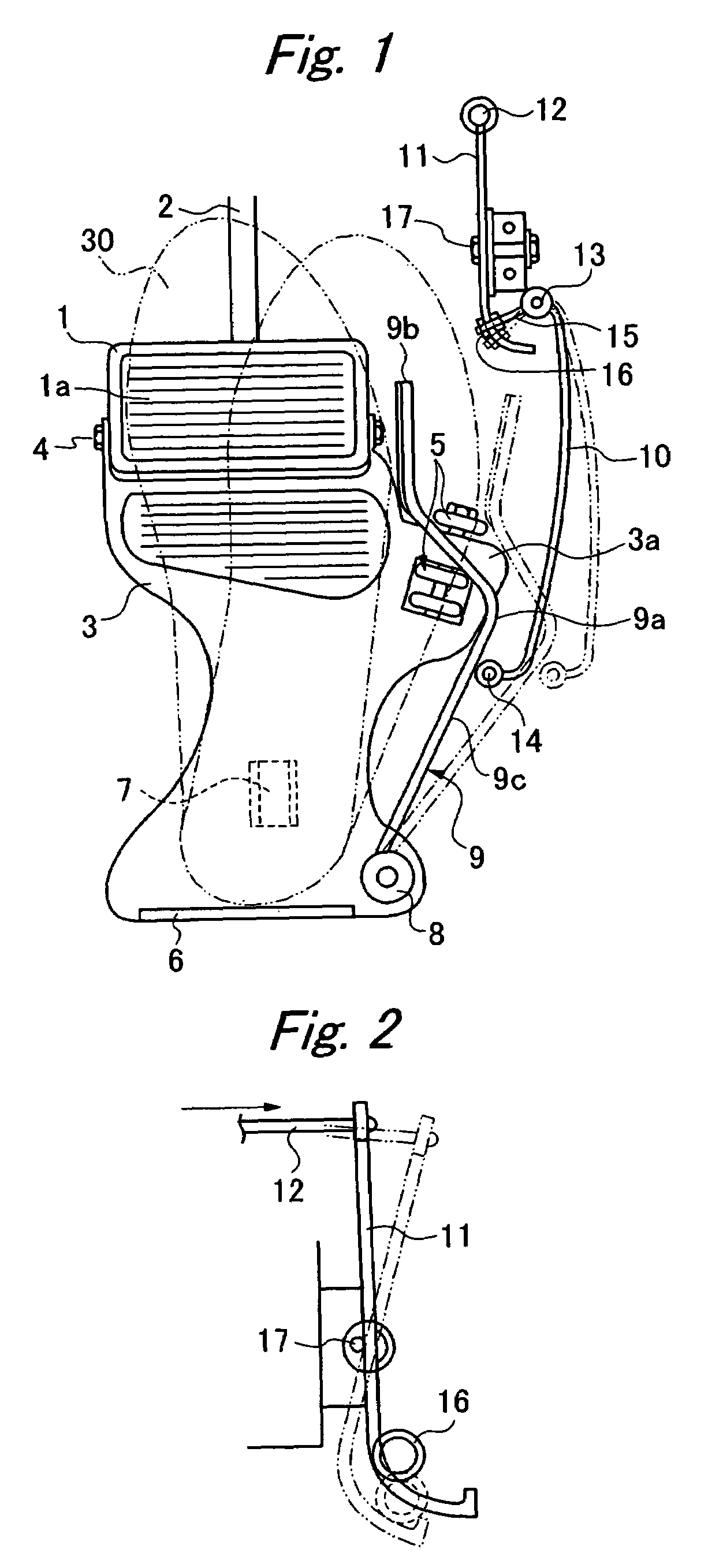
[0023]FIG. 1 is a schematic plan view of an automobile accelerator and brake pedal device. A brake pedal 1 of the device is an ordinary one such as found in an ordinary automobile in which the braking operation is made by stepping on. As is well known, such brake pedal 1 is fixed to one end of a brake arm 2, and the other end of the brake arm 2 is operatively connected to the braking system including a hydraulic device. A rubber sheet 1a is stuck on the surface of the brake pedal 1 to prevent a driver's shoe from slipping.
[0024]An auxiliary pad 3 is connected to the brake pedal 1 via a joint member 4 such as a bolt, and the auxiliary pad 3 has an outward-curved projection 3a formed on its right side. The outward-curved projection 3a has rolls 5 mounted thereon. These rolls 5 effectively reduce the friction which resists the rightward movement of the shoe from the...
PUM
 Abstract
Description
Claims
Application Information