Printer with cutter

Inactive Publication Date: 2010-06-10
SEIKO INSTR INC
View PDF8 Cites 20 Cited by
  • Summary
  • Abstract
  • Description
  • Claims
  • Application Information

AI Technical Summary

Benefits of technology

[0040]With this configuration, the movable blade and the fixed blade retreat in the directions orthogonal to each other, respectively. Thus, in the case of occurrence of paper jam or the like, even when the movable blade is stopped during sliding and retreating of the both blades is difficult, the both blades neither interfere with each other due to contact therebetween nor retreat while catching the recording sheet therebetween at the time of retreating of the both blades. As a result, it is possible to easily release the contact pressure between the both blades, and to promptly release the recording sheet caught between the both blades. Thereafter, by removing the recording sheet caught between the both blades, it is possible to easily perform restoring work for paper jam

Problems solved by technology

Incidentally, in each of the above-mentioned thermal printers, there may arise a problem that the movable blade is stopped during sliding due to such phenomena that foreign matters are caught between the fixed blade and the movable blade, that the recording sheet drawn out of the paper roll is caught (so-called paper jam), that blades bite each other in a process of

Method used


Image

  • Printer with cutter
  • Printer with cutter
  • Printer with cutter

Examples


first embodiment

[0059](Thermal Printer)

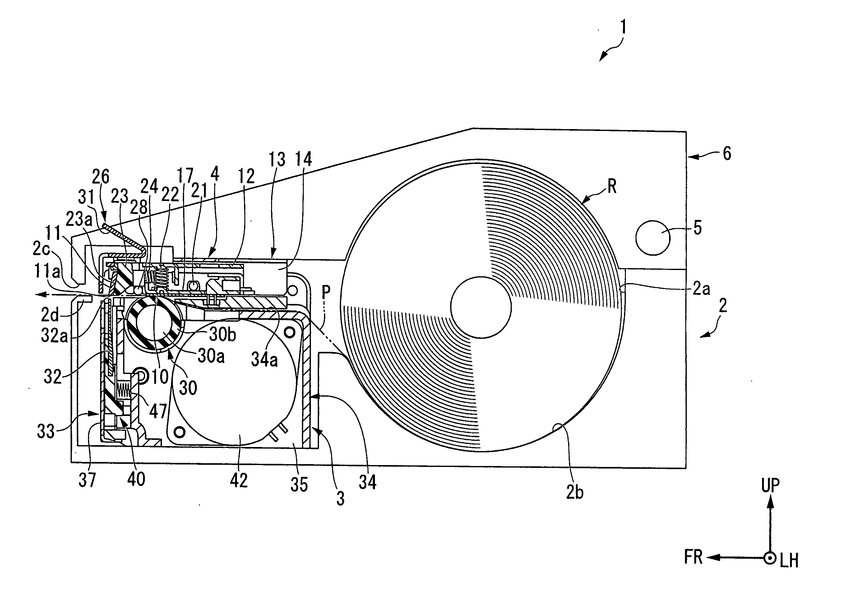
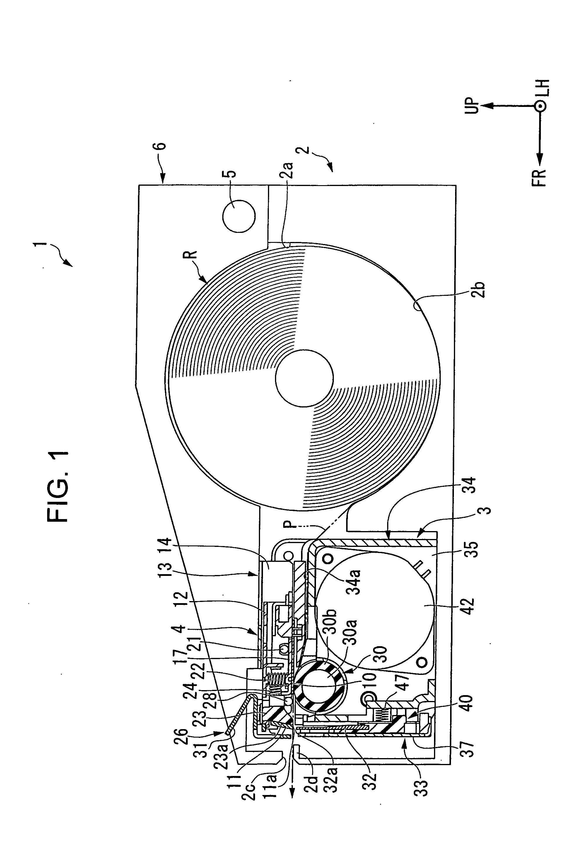
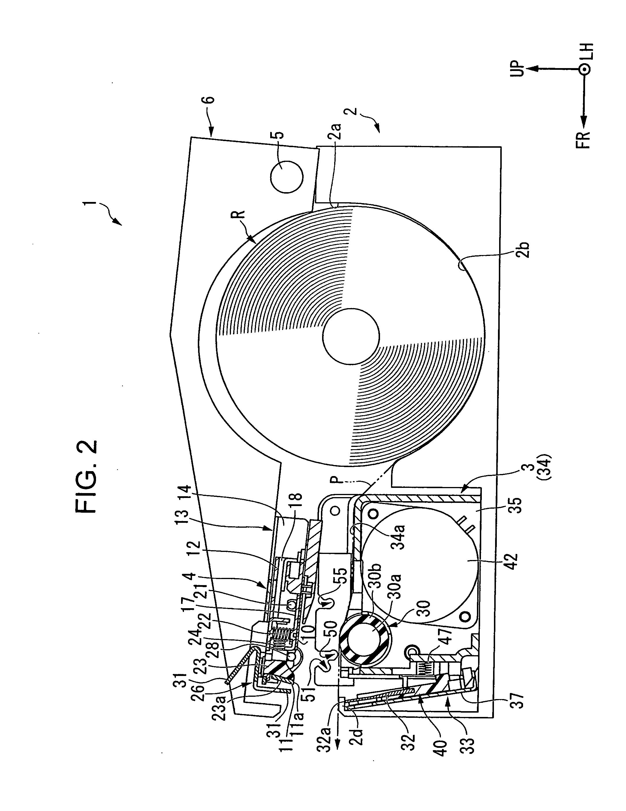
[0060]Next, an embodiment of the present invention is described with reference to the drawings. Note that, in this embodiment, a thermal printer is described as an example of a printer with a cutter. FIGS. 1 and 2 are sectional views of the thermal printer. FIG. 1 illustrates a state in which an open-close door is closed, and FIG. 2 illustrates a state in which the open-close door is opened. Note that, in the following description, symbols FR, LH, and UP indicate front, left, and upper sides, respectively.

[0061]As illustrated in FIGS. 1 and 2, a thermal printer 1 is a so-called clamshell printer in which printing is performed on a recording sheet P drawn out of a paper roll R, and then this recording sheet P is appropriately cut to thereby be used as a ticket, receipt, or the like. That is, the thermal printer 1 mainly includes a casing 2, an open-close door 6 provided openable and closable with respect to the casing 2, a main body unit 3 incorporated into the...

second embodiment

[0132]Next, a second embodiment of the present invention is described with reference to FIGS. 12 and 13. FIG. 12 is an enlarged side view corresponding to the part A of FIG. 3 in the second embodiment. The second embodiment differs from the above-mentioned first embodiment in that a movable blade frame is biased toward the home position, and in a configuration of a ratchet mechanism constituted by a detachable unit and a main body unit. Note that, in the following description, the same components as those in the first embodiment are denoted by the same reference symbols.

[0133]As illustrated in FIG. 12, a pair of engagement pins 128 is formed on front portions of both side surfaces 118 of a fixed blade frame 112 of a detachable unit 104 of this embodiment. The engagement pins 128 protrude from the both side surfaces 118 in the lateral directions in the front of the auxiliary shaft 21.

[0134]Meanwhile, a pair of recesses 150 is formed in upper peripheral edges of both side plates 135 o...

third embodiment

[0146]Next, a third embodiment of the present invention is described with reference to FIGS. 14 and 15. FIG. 14 is an enlarged side view corresponding to the part A of FIG. 3 in the third embodiment. The third embodiment differs from the above-mentioned second embodiment in a configuration of a ratchet mechanism constituted by a detachable unit and a main body unit. Note that, in the following description, the same components as those in each of the first and second embodiments are denoted by the same reference symbols.

[0147]As illustrated in FIG. 14, a pair of engagement pins 255 is formed on upper portions of both side plates 235 of a main body frame 234 of a main body unit 203. The engagement pins 255 protrude in the lateral directions from the upper peripheral edges at the center portions in the longitudinal direction of the side plates 235.

[0148]Further, a pair of hook portions 253 having a triangular shape in plan view and extending rearward is formed at upper rear end edges o...


PUM


Abstract

Provided is a printer with a cutter, which can easily restore, even when there arises a problem that a movable blade is stopped during sliding due to paper jam or the like, the movable blade to a state before the problem arises, reliably perform positioning between a movable blade frame and a detachable unit, and improve printing accuracy and cutting accuracy. A detachable unit (4) turns in a sliding direction of a movable blade (32) from a mounted position to a dismounted position. Meanwhile, a movable blade frame (33) turns in a direction orthogonal to the sliding direction of the movable blade (32) from a home position to a separated position. Thus, the both blades (32 and 11) retreat in directions orthogonal to each other, respectively.

Description

BACKGROUND OF THE INVENTION[0001]1. Field of the Invention[0002]The present invention relates to a printer with a cutter, which can appropriately cut a recording sheet drawn out of a paper roll after printing is performed on the recording sheet.[0003]2. Description of the Related Art[0004]At present, there are provided various kinds of many thermal printers, in which printing is performed by pressing a thermal head against a special recording sheet (heat-sensitive sheet) which changes in color when heat is applied thereto, and by developing color on the recording sheet by heating. In particular, smooth characters and multicolor graphics can be printed without using toner, ink, and the like, and hence the thermal printers are preferably used for printing of various kinds of labels, receipts, and tickets.[0005]As represented by the thermal printers as described above, there are known many printers with a cutter including a cutter mechanism for automatically cutting the printed recordi...

Claims


Application Information

Patent Timeline
IPC IPC(8): B41J11/00
CPCB26D1/085B26D5/02B41J11/70B26D7/2614B41J11/006B26D7/00
Inventor KAWAGUCHI, KOUJI
Owner SEIKO INSTR INC
Why Eureka
Try Eureka