

Construction Machine
- Summary
- Abstract
- Description
- Claims
- Application Information
AI Technical Summary
Benefits of technology
Problems solved by technology
Method used
Image

Examples
first embodiment
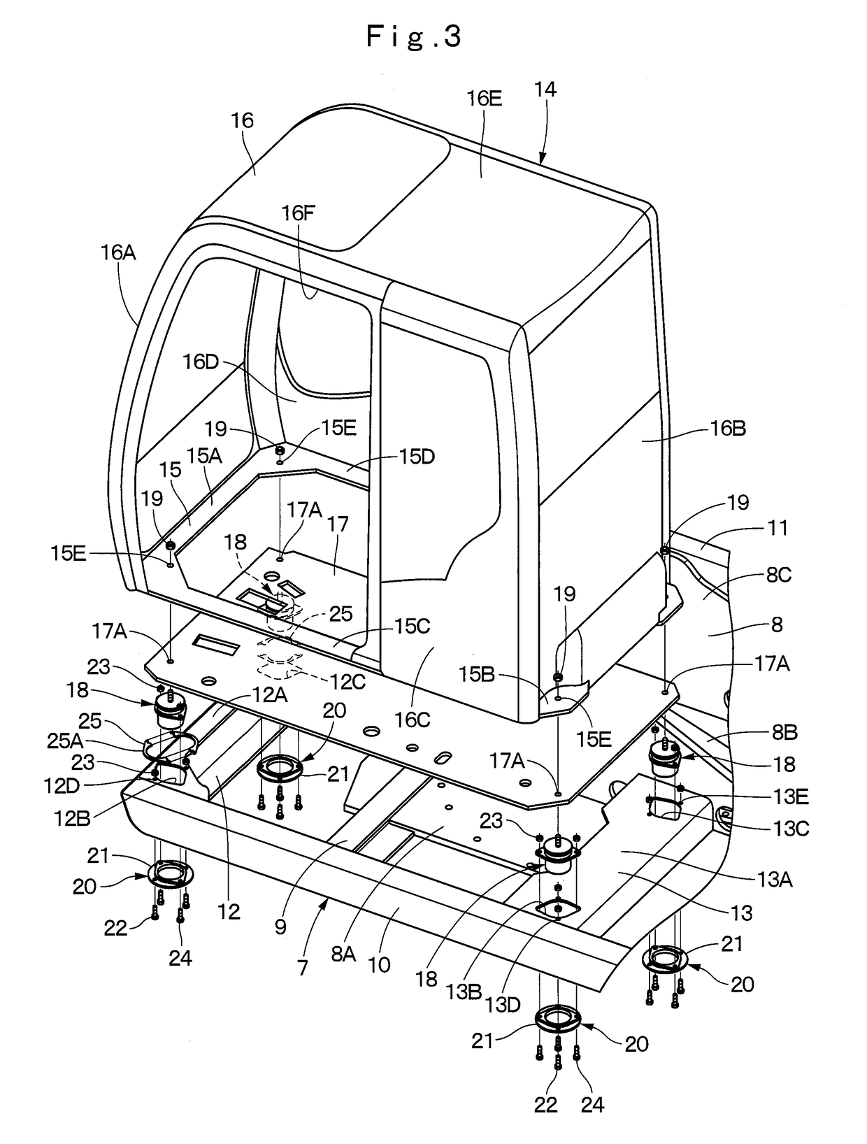
[0033]In addition, FIG. 4, FIG. 5, FIG. 8 to FIG. 10 used in the first embodiment schematically show, for easy understanding of amounting relation of a revolving frame 7, vibration isolating members 18 and intermediate connecting members 20, frame bolts 22 and vibration isolating bolts 24 to be described later, which are assumed to exist on the same cross section.
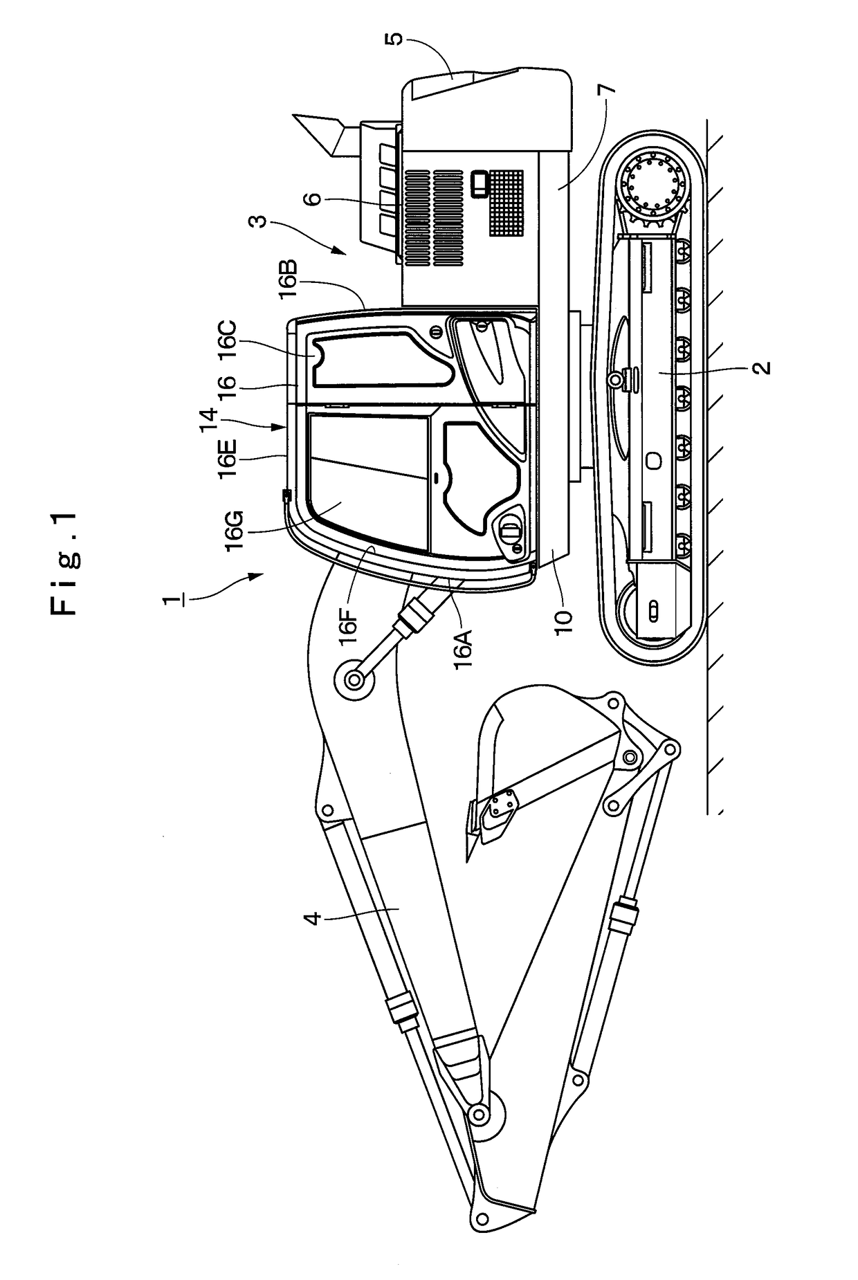
[0034]In FIG. 1, a hydraulic excavator 1 as a representative example of construction machines is provided with a vehicle body formed of an automotive lower traveling structure 2 of a crawler type and an upper revolving structure 3 that is mounted on the lower traveling structure 2 to be capable of revolving thereon. A front device 4 is disposed on a front side of the upper revolving structure 3 to be capable of tilting and lifting thereto, and an excavating work of earth and sand is performed by the front device 4.
[0035]The upper revolving structure 3 includes the revolving frame 7 to be described later, a counterweight 5 d...
second embodiment
[0074]Next, FIG. 11 and FIG. 15 show the present invention. The second embodiment exemplifies a case of performing adjustment of lowering a left front side and a left rear side of a cab.
[0075]A vibration isolating member according to the present embodiment includes a main body part having a damping function of vibrations, a flange part disposed on an outer periphery of the main body part and a fastening part that projects toward an upper side from the main body part and is mounted on a bottom plate of a cab. An intermediate connecting member has a connecting tool that supports the vibration isolating member to a vehicle body frame, and a spacer that adjusts a height position of the cab to the vehicle body frame. The spacer is a downside spacer that is arranged between a lower surface of the vehicle body frame and an upper surface of the connecting tool of the intermediate connecting member to lower the height position of the cab. It should be noted that in the second embodiment, com...
third embodiment
[0085]The height adjustment part 43 forming the intermediate connecting member 41 is disposed to project upward in the inner diameter side of the connecting tool 42 to face the flange part 18B of the vibration isolating member 18. The height adjustment part 43 is formed in a diamond shape that is the same as or close to that of the flange part 18B of the vibration isolating member 18. Here, a height dimension ΔH4 of the height adjustment part 43 is, as indicated at the following Formula 4, set to a dimension different from the plate thickness dimension ΔH1 of the flat plate part 12A of the front side cab support frame 12. Thereby, the intermediate connecting member 41 is used instead of the intermediate connecting member 20 of the standard specification, making it possible to adjust the height position of the cab 14.
ΔH4≠ΔH1 [Formula 4]
[0086]As shown in FIG. 19, the third embodiment exemplifies a case of heightening the height position of the front side of the cab 14 to the height ...
PUM
 Abstract
Description
Claims
Application Information