Device and method to complete reinforcement cages

Inactive Publication Date: 2002-09-19
M E P MASCH ELECTRONICS PIEGATRICI SPA
View PDF29 Cites 2 Cited by
  • Summary
  • Abstract
  • Description
  • Claims
  • Application Information

AI Technical Summary

Benefits of technology

0017] Therefore, the operators can easily position and attach at least one rod according to design specifications each time, in correspondence with said specific corner of at least some of the stirrups of the pre-cage, said corner being always in a position where the operators can work easily.
0018] By progressively repeating the cycle of rotation of the cage and subsequent attachment of the rods according to design specifications for all or at least some of the corners of the stirrups, the cage can be discharged from the machine with all the rods already positioned and attached at least in correspondence with the corners; this facilitates any possible further steps to complete

Problems solved by technology

Inserting and attaching the longitudinal rods according to design specifications inside the perimeter of the stirrups is a difficult operation, however, especially if the cages to be made, and hence the relative rods, are very long; these operations entail risks to the safety of the workers, a large work force, the need for equipment and risks of damaging the material.
With this device, however, the rods are not constrained to the stirrups,

Method used


Image

  • Device and method to complete reinforcement cages
  • Device and method to complete reinforcement cages
  • Device and method to complete reinforcement cages

Examples


Embodiment Construction

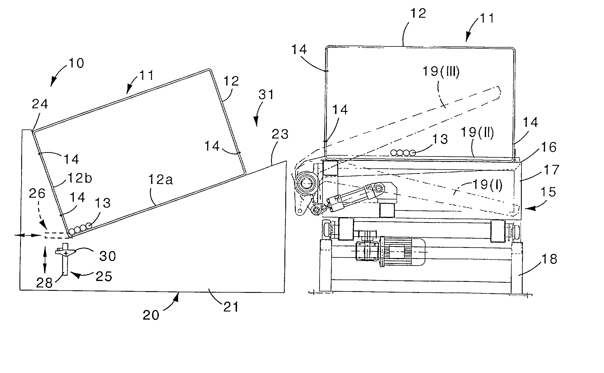
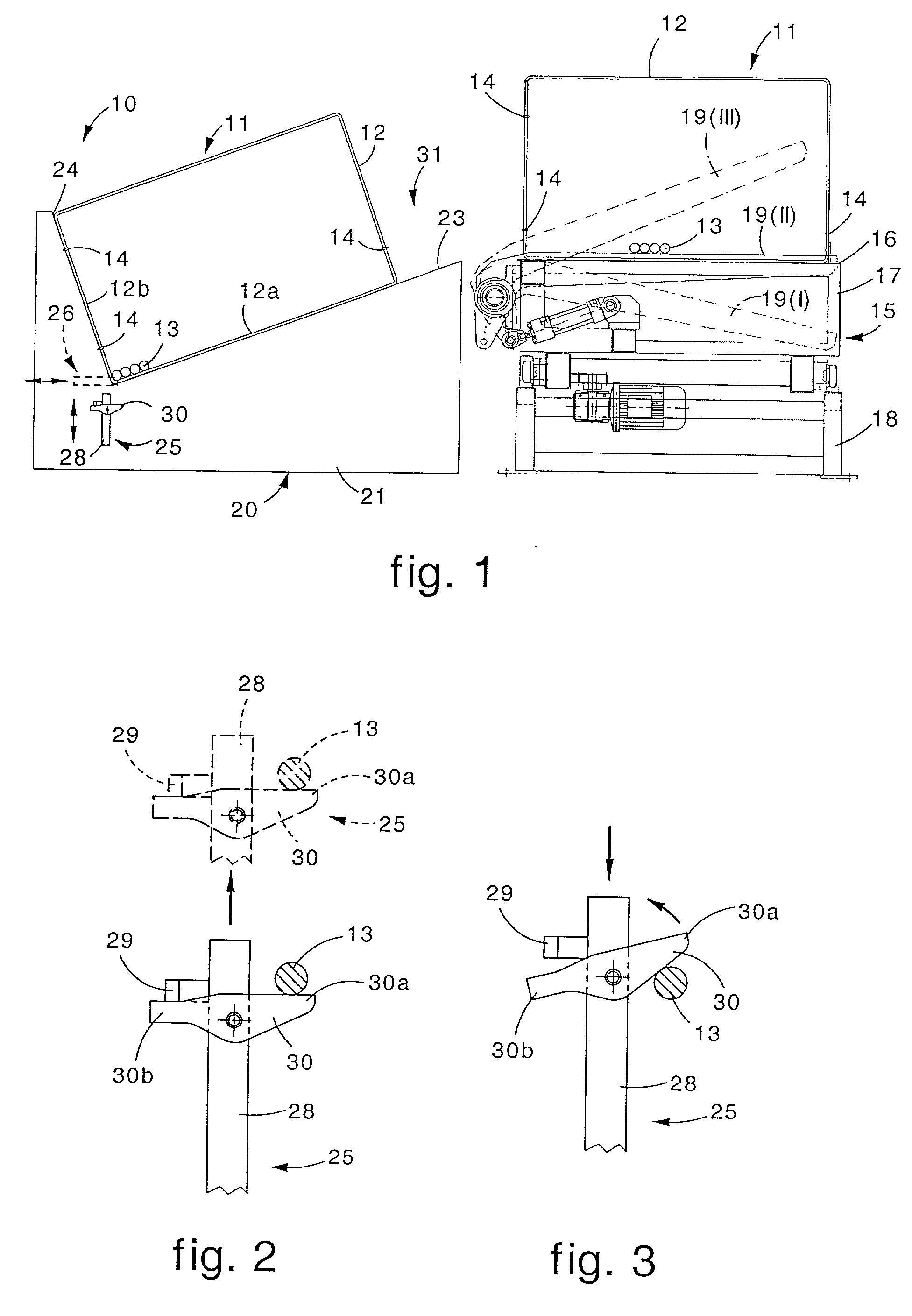
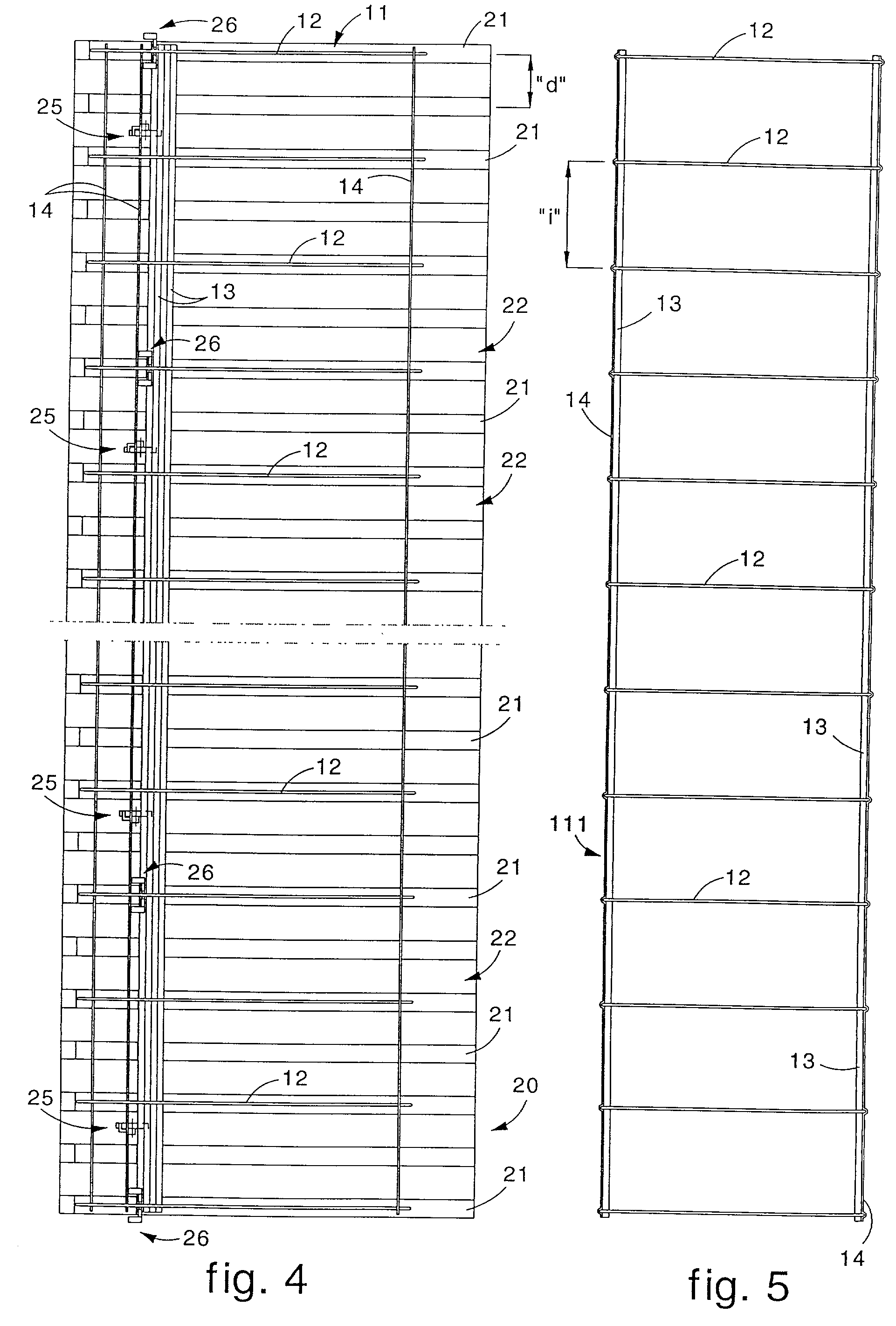
[0028] In the attached Figures, the number 10 denotes generally a device according to the invention able to position and attach longitudinal rods 13 according to design specifications at least in correspondence with the inner corners of stirrups 12 with a closed polygonal profile of a pre-cage 11, in order to obtain a complete cage 111. In this case, the stirrups 12 are arranged with an interaxis "i", they are rectangular and comprise four inner corners .alpha.,.beta.,.gamma.,.delta.where at least one longitudinal rod 13 is provided to be attached. The device 10 according to the invention is located next to a device 15 suitable to form a pre-cage 11, wherein said longitudinal rods 13 are inserted inside the perimeter of the stirrups 12 in the course of the formation of the pre-cage 11 (FIG. 1).

[0029] In this case, the pre-cage 11 consists of three auxiliary profiles 14 and a plurality of stirrups 12; the auxiliary profiles 14 are loop-shaped in correspondence with the stirrups 12 an...


PUM

PropertyMeasurementUnit
Distanceaaaaaaaaaa
Displacementaaaaaaaaaa

Abstract

Device (10) and method to complete reinforcement cages comprising a plurality of longitudinal rods (13) and stirrups (12) separated at intervals along the rods (13). The device (10) is used to position the longitudinal rods (13) in correspondence with the inner corners of the stirrups (12), and comprises supporting means defining a plane (23, 123) which supports a pre-cage (11) comprising the stirrups (12) and the longitudinal rods (13) arranged free within the perimeter of the stirrups (12). One corner of the stirrups (12) rests on, and faces towards the outside of, the plane (23, 123). Lifting elements (25) lift the pre-cage (11) to overturn it partly and in sequence on the plane (23, 123), so as to take on each occasion a different corner of the stirrups (12) into an adjacent position facing towards the outside of the plane (23, 123).

Description

FIELD OF THE INVENTION[0001] The invention concerns a device and a method to complete reinforcement cages employed in reinforced concrete structures such as beams, pillars or foundations.[0002] The invention is intended to facilitate the operations to position and attach a plurality of longitudinal rods, arranged free inside the perimeter of the stirrups, at least in correspondence with the corners of the stirrups.[0003] The invention is applied to cage-forming machines intended to form reinforcement cages or pre-cages in a substantially automatic fashion.BACKGROUND OF THE INVENTION[0004] In the state of the art, metal cages employed as reinforcement in reinforced concrete structures comprise a plurality of longitudinal rods to which stirrups separated at intervals lengthwise are associated.[0005] These cages can be assembled in two successive steps, by first preparing a substantially standardized pre-cage, consisting of the stirrups held together in the positions set out in the des...

Claims


Application Information

Patent Timeline
IPC IPC(8): B21F27/12
CPCB21F27/121B21F27/125Y10T29/53
Inventor GIORGIO, DEL FABROMARCELLO, DEL FABRO
Owner M E P MASCH ELECTRONICS PIEGATRICI SPA
Why Eureka
Try Eureka