Filter frame

Active Publication Date: 2015-01-15
CANON KK
View PDF5 Cites 13 Cited by
  • Summary
  • Abstract
  • Description
  • Claims
  • Application Information

AI Technical Summary

Benefits of technology

[0013]A principal object of the present invention is to provide a filter frame capable of not only holding a pleated filter at a pre

Problems solved by technology

When the temperature in the main assembly of the image forming apparatus excessively increases, e.g., a member such as a plastic-made paper feeding guide mounted in the apparatus main assembly is thermally deformed, thus causing paper jamming of feeding paper in some cases.
Further, depending on an environment of a disposition place of the image forming apparatus, such a phenomenon that dirt and dust are accumulated in the apparatus main assembly or are raised and floated by vibration due to an operation of the image forming apparatus or air blowing by a fan or the like occurs.
When the dirt and the dust are excessively accumulated or floated, e.g., the dirt and the dust are deposited on a surface of the sheet to cause lack of a part of an image when the image is transferred onto the sheet is some cas

Method used


Image

  • Filter frame
  • Filter frame
  • Filter frame

Examples


embodiment 1

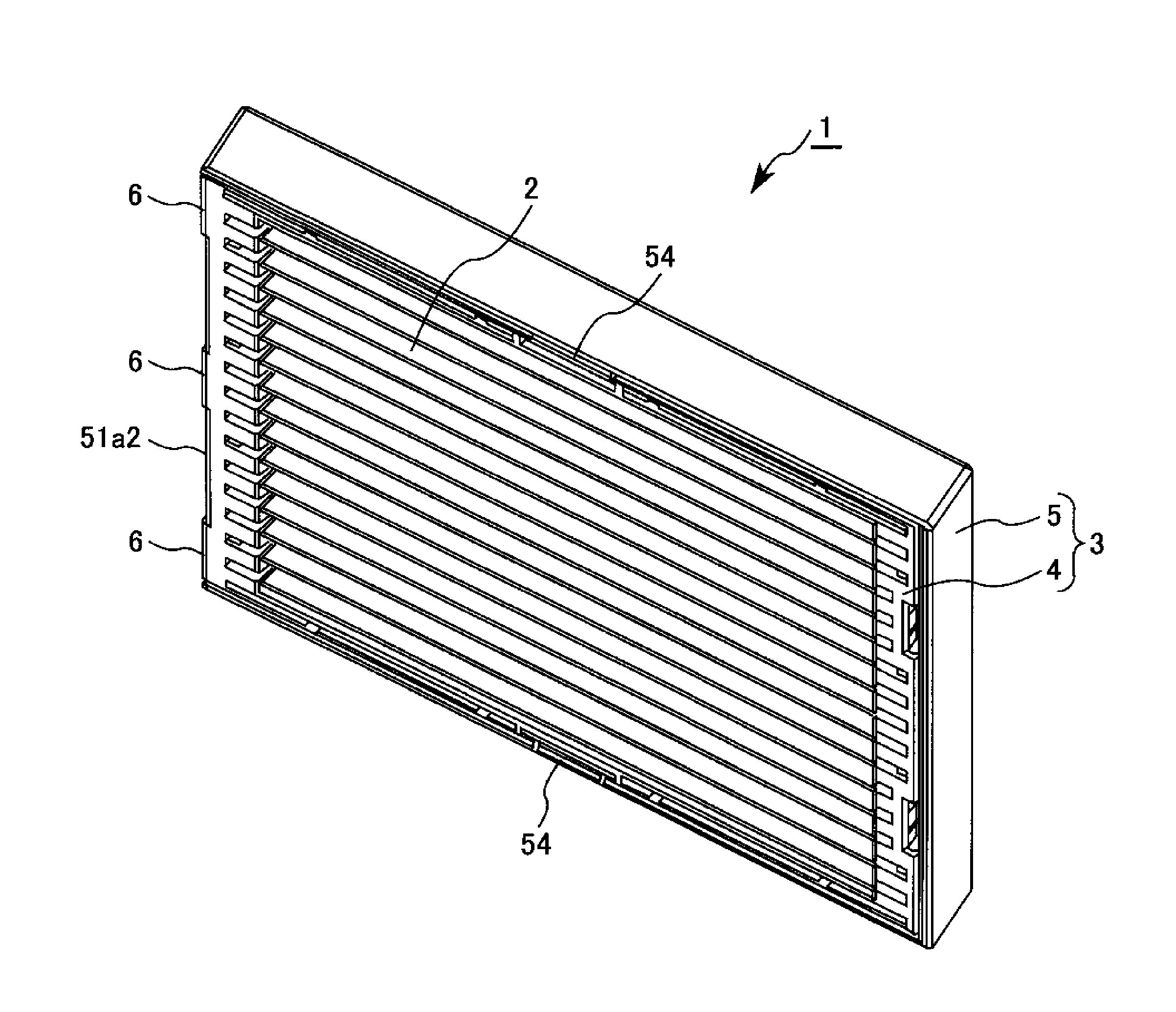
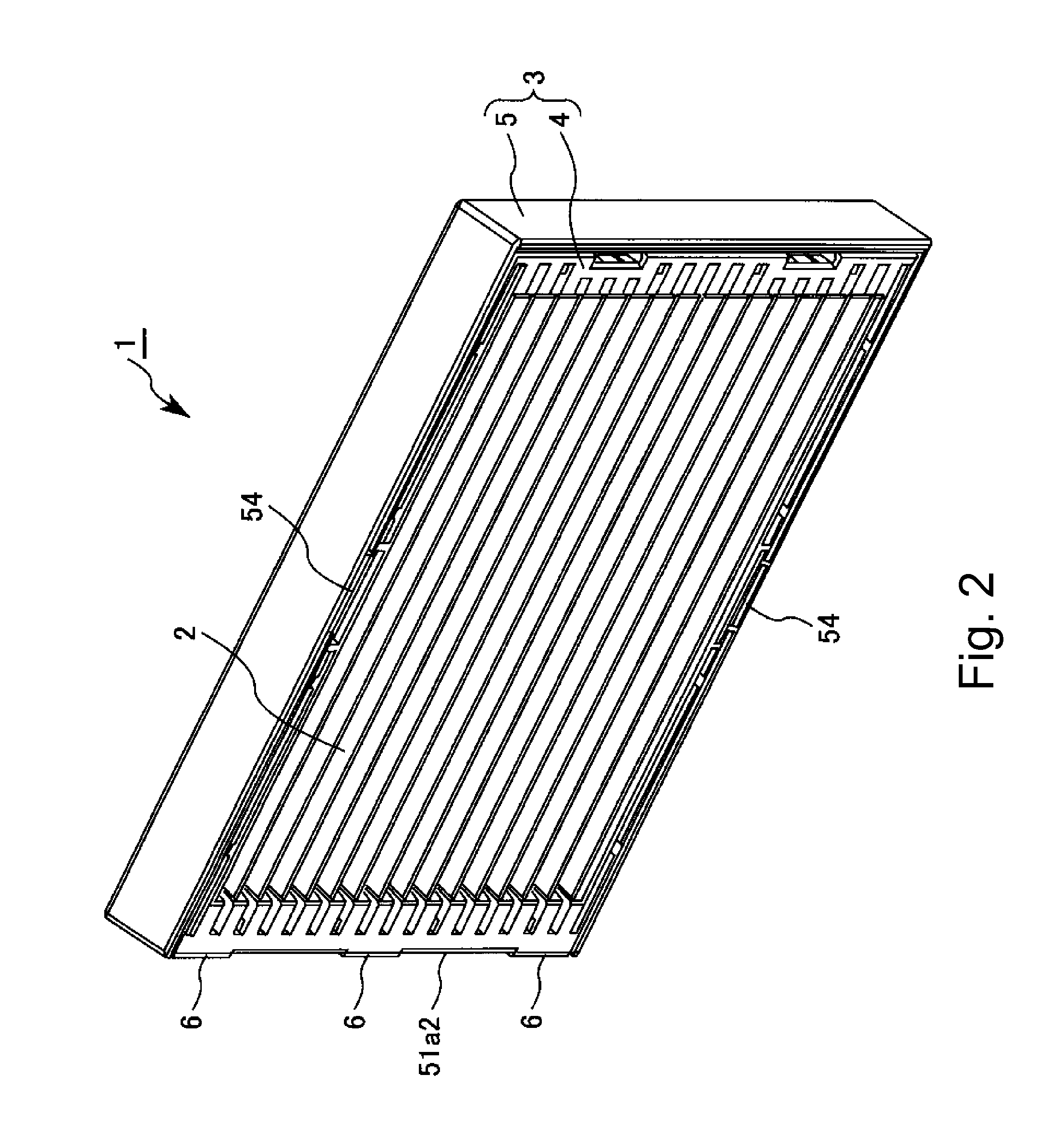
[0029]In this embodiment, the filter frame according to the present invention is implemented as a filter frame for a dust collecting filter of the filter assembly provided in an exhaust path of an exhaust duct of an image forming apparatus.

1. Image Forming Apparatus

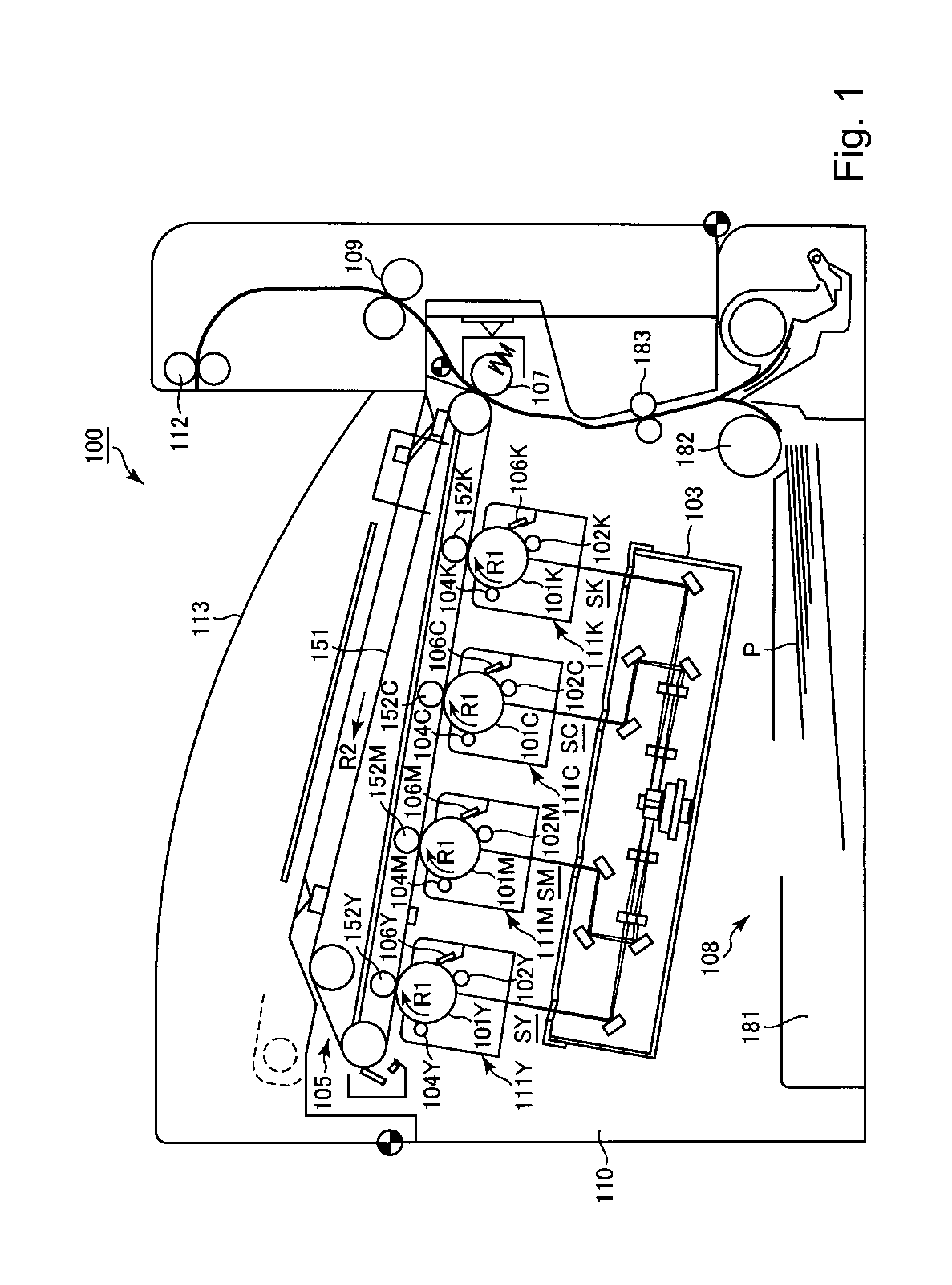
[0030]First, a general structure and an operation of the image forming apparatus in the present invention will be described. FIG. 1 is a schematic sectional view showing the general structure of an image forming apparatus 100 in this embodiment. The image forming apparatus 100 in this embodiment is a laser beam printer of an intermediary transfer type in which a full-color image can be formed by using electrophotography.

[0031]The image forming apparatus 100 includes, as a plurality of image forming portions, first to fourth image forming portions (stations) SY, SM, SC and SK for forming toner images of yellow (Y), magenta (M), cyan (C) and black (K), respectively. The image forming portions SY, SM, SC and SK have the subs...


PUM


Abstract

A filter frame for holding a filter provided with a plurality of folds so as to alternately form ridges and troughs includes: a first frame portion including a first holding portion, having a side corresponding to a first side of the filter, for holding the filter; a positioning portion, provided on the first holding portion, for determining a position of the filter; and a second frame portion including a second holding portion for holding the filter by sandwiching the filter between the first and second holding portions. The second holding portion is provided so as to be capable of opposing the first holding portion via the filter and has a side corresponding to a second side of the filter.

Description

FIELD OF THE INVENTION AND RELATED ART[0001]The present invention relates to a filter frame for use with a dust collecting filter or the like provided in an exhaust duct in an image forming apparatus.[0002]For example, in a main assembly of the image forming apparatus, such as a copying machine or a printer, of an electrophotographic type, a plurality of electrical parts (components) such as a motor, a fan and a power source substrate are mounted. These parts are disposed inside the apparatus main assembly as driving sources and the like for various constituent elements for performing a process starting from sheet feeding to discharge of an image-formed product via image formation. Such electrical parts generate heat from a main body thereof, and when the heat is accumulated in the main assembly of the image forming apparatus, a temperature in the apparatus main assembly increases. When the temperature in the main assembly of the image forming apparatus excessively increases, e.g., ...

Claims


Application Information

Patent Timeline
IPC IPC(8): B01D46/52
CPCB01D46/521B01D46/0002B01D46/52B01D2265/028G03G21/206B01D46/0005B01D46/10B01D46/523
Inventor YAMAGUCHI, YOSHIMASUUNO, TAKASHI
Owner CANON KK
Why Eureka
Try Eureka