Motor Vehicle, Indicating Device and Operating Method

a technology of indicating device and motor vehicle, which is applied in the measurement of vehicle tractive/propulsive power, instruments, transportation and packaging, etc., can solve the problems of vehicle accelerating unintentionally with more or less speed than the intended speed, and the use of recuperated energy is significantly less efficien

Active Publication Date: 2009-01-29
DR ING H C F PORSCHE AG
View PDF24 Cites 27 Cited by
  • Summary
  • Abstract
  • Description
  • Claims
  • Application Information

AI Technical Summary

Benefits of technology

[0026]It is possible to provide in an advantageous manner a switch-off dead time operational control element, with which the driver can set any desired switch-off dead time. It is also advantageous to provide an additional drive pedal hysteresis operational control element, with which the driver can set the drive pedal hysteresis.
[0027]The switch-off dead time operational control element and the drive pedal operational control element may also be combined in an advantageous manner. Then the result is an operational control element for the coasting indicating device, with which the degree of usage of the coasting mode

Problems solved by technology

Yet in this context there are two problems.
Yet, even recuperation and then use of the recuperated energy is significantly less efficient than coasting, since during coasting the kinetic energy is maintained and is reduced only by unavoidable driving resistances.
However, in the case of recuperation only approximately 50% of the recuperated energy or less can be used again at a later date for accelerating.
If the driver performs the activation, there is the problem that it is difficult for him to detect this state, so that, o

Method used


Image

  • Motor Vehicle, Indicating Device and Operating Method
  • Motor Vehicle, Indicating Device and Operating Method
  • Motor Vehicle, Indicating Device and Operating Method

Examples


Embodiment Construction

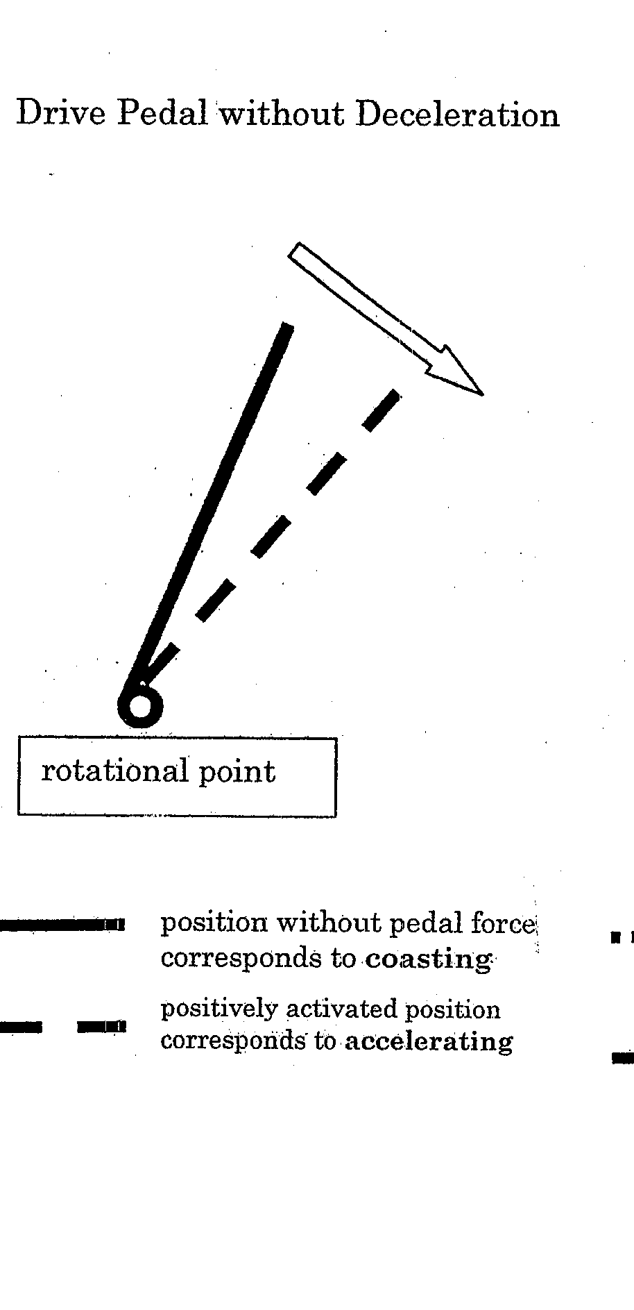
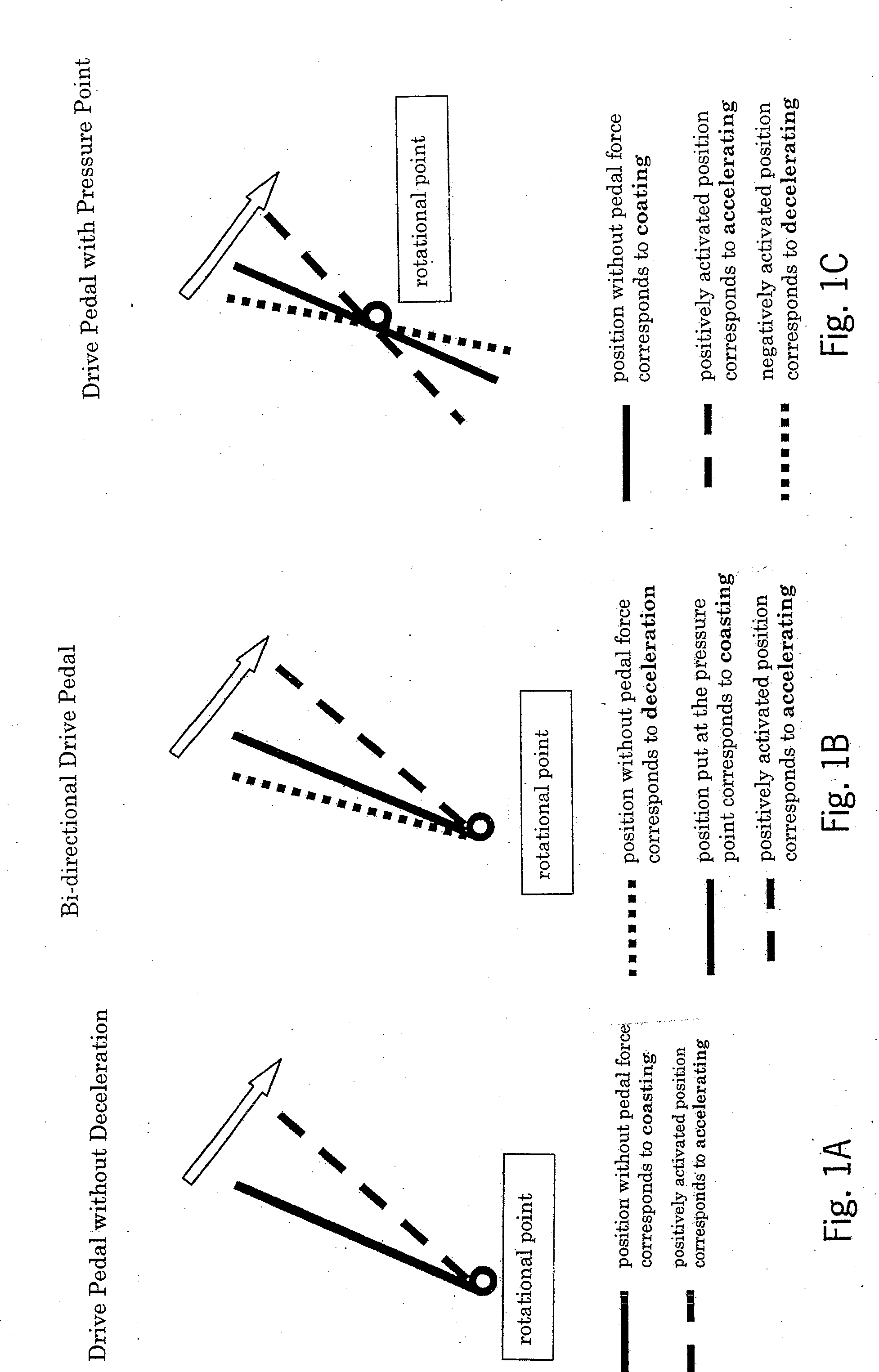
[0033]FIG. 1 is a schematic drawing of the haptic indication with the use of the user interface drive pedal. The drawings 1B and 1C show the embodiments of a haptic drive pedal. The rotational point of the drive pedal is illustrated by the small circles in FIG. 1. In the embodiments of the haptic drive pedal the conventional drive pedal is expanded in such a manner that a corresponding activation by, for example, an actuator, can signal to the driver the pedal positions, determined by the algorithm, in the form of a pressure point.

[0034]FIG. 1A shows a conventional drive pedal. The non-activated position that is, the position in which no force is applied corresponds to a deceleration with the drive unit.

[0035]FIG. 1B shows a drive pedal with a pressure point. In this case the non-activated position that is, the position in which no force is applied and which corresponds to coasting (the marked position) signifies a deceleration as a function of the braking torque of the drive unit.

[...


PUM


Abstract

An indicating device for a motor vehicle and an operating method are provided. The motor vehicle includes a drive train with at least one drive unit. The indicating device shows in a differentiable manner to the driver the drive states of accelerating, unpowered driving (coasting) and decelerating using the drive train, and at a minimum signals to the driver when the coasting state exists so as to permit the driver to optimize efficient use of the vehicle.

Description

CROSS-REFERENCE TO RELATED APPLICATIONS[0001]This application claims the priority of German Application No. 10 2007 035 426.8, filed Jul. 28, 2007, the disclosure of which is expressly incorporated by reference herein.BACKGROUND AND SUMMARY OF THE INVENTION[0002]The present invention relates to a motor vehicle, an indicating device and an operating method.[0003]In this case the motor vehicle comprises at least one drive unit, which may be disengaged from the rest of the drive train by, for example, a suitable clutch. The object of the invention is to indicate to the driver when he is in a running state, in which the vehicle would continue to drive with the same longitudinal acceleration, even if the clutch between the drive unit and the rest of the drive train were disengaged. This running state is called “coasting” and makes possible an operating mode that saves energy by switching off the drive unit when the clutch is disengaged or by operating the drive unit at least t a reduced ...

Claims


Application Information

Patent Timeline
IPC IPC(8): G06F17/00
CPCB60K26/021B60W2510/0657B60W2510/0208G01L5/13
Inventor JACOBI, STEFANHOFMANN, ROLF
Owner DR ING H C F PORSCHE AG
Why Eureka
Try Eureka