Spider Web Interconnect Topology Utilizing Multiple Port Connection

a topology and multi-port technology, applied in computing, instruments, electric digital data processing, etc., can solve the problems of affecting data transfer rates, and reducing the number of drop buses

Active Publication Date: 2009-01-29
LENOVO GLOBAL TECH INT LTD
View PDF3 Cites 8 Cited by
  • Summary
  • Abstract
  • Description
  • Claims
  • Application Information

AI Technical Summary

Problems solved by technology

The higher frequencies required to support the faster data rates can not be supported on multi-drop busses, driving topologies to point-to-point busses.
The directional turn-around penalties on high speed busses with multiple transfers in flight tend to be too extreme, resulting in a transition from shared bidirectional busses to separate unidirectional busses.
The power and area expense of the electrical I / O used to drive each unidirectional high speed bus interconnect wire has driven the transition from wide parallel busses to narrow serial busses.
Also, when serial high speed unidirectional busses develop faults or are temporarily congested, data transfer rates can be impacted.

Method used


Image

  • Spider Web Interconnect Topology Utilizing Multiple Port Connection
  • Spider Web Interconnect Topology Utilizing Multiple Port Connection
  • Spider Web Interconnect Topology Utilizing Multiple Port Connection

Examples


Embodiment Construction

[0018]A preferred embodiment of the invention is now described in detail. Referring to the drawings, like numbers indicate like parts throughout the views. As used in the description herein and throughout the claims, the following terms take the meanings explicitly associated herein, unless the context clearly dictates otherwise: the meaning of “a,”“an,” and “the” includes plural reference, the meaning of “in” includes “in” and “on.”

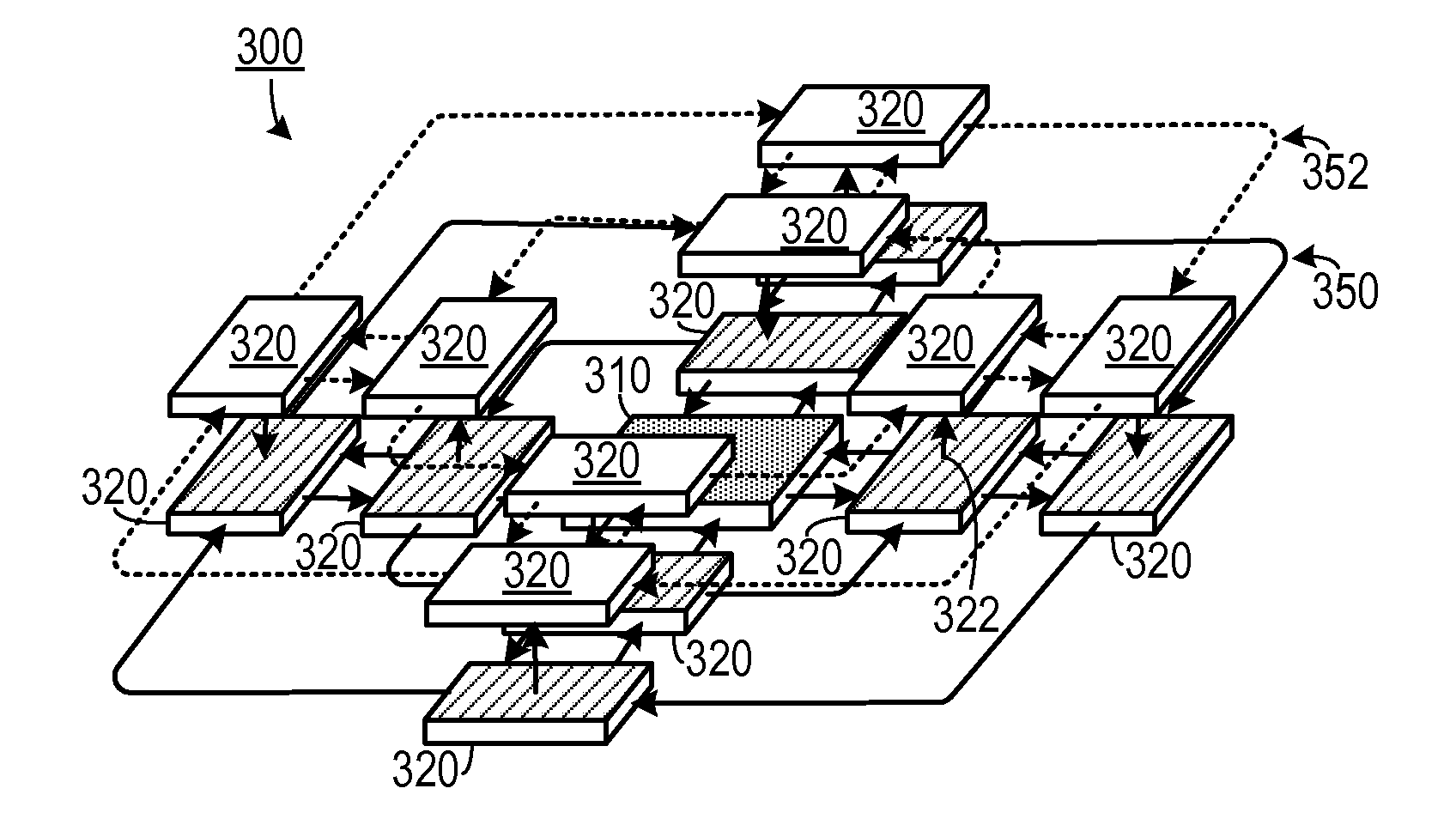
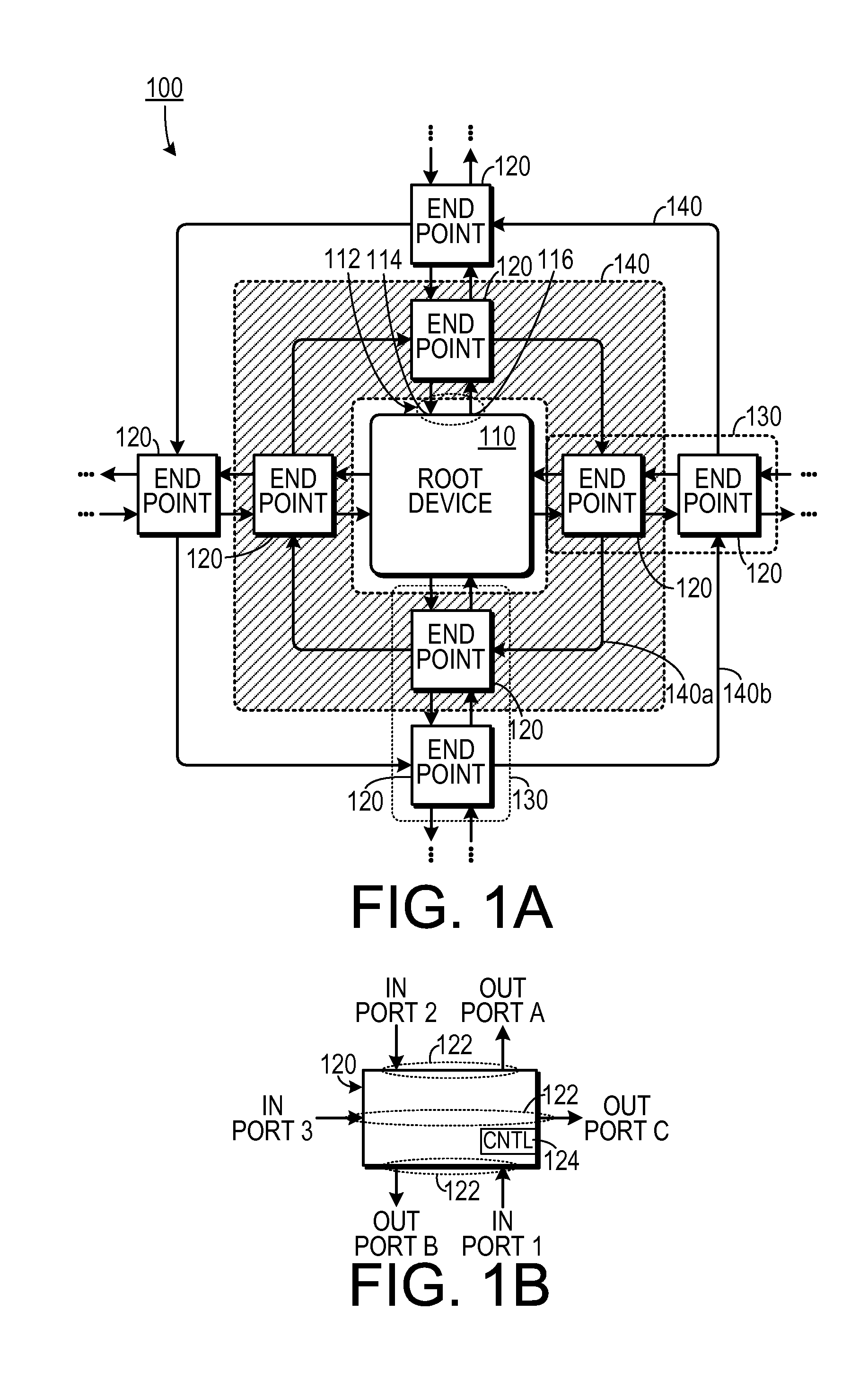
[0019]As shown in FIG. 1A, one embodiment is a data communications apparatus 100 that includes a central device 110 and a plurality of communication devices a plurality of communication devices 120. The central device 110 includes a plurality of central port pairs 112 (only one of which is pointed to in the figure for the sake of clarity) and each central port pair 112 include an input port 114 and an output port 116. Each of the communication devices 120 is arranged in a spoke and ring configuration in which each communication device 120 is part of a co...


PUM


Abstract

A data communications apparatus includes a central device and a plurality of communication devices. The central device includes a plurality of central port pairs, in which each central port pair includes an input port and an output port. The plurality of communication devices is arranged in a spoke and ring configuration, in which each communication device is part of a communication spoke. Each communication spoke is in communication with a different central port pair. Each communication device is also a part of a communication ring, so that each communication device in a selected communication ring belongs to a different communication spoke.

Description

BACKGROUND OF THE INVENTION[0001]1. Field of the Invention[0002]The present invention relates to computer systems and, more specifically, to a computer system in which a root device communicates with a plurality of other devices.[0003]2. Description of the Prior Art[0004]In computer systems, increasing processor performance is driving the need for higher bandwidth on input-output (I / O) interfaces, memory interfaces and inter-processor interconnects. Generally, these interfaces are changing from multi-drop bidirectional parallel busses to point-to-point high speed unidirectional serial busses. The higher frequencies required to support the faster data rates can not be supported on multi-drop busses, driving topologies to point-to-point busses.[0005]The directional turn-around penalties on high speed busses with multiple transfers in flight tend to be too extreme, resulting in a transition from shared bidirectional busses to separate unidirectional busses. The power and area expense o...

Claims


Application Information

Patent Timeline
Patent Type & Authority Applications(United States)
IPC IPC(8): G06F13/36G06F12/00
CPCG06F13/1684
Inventor BARTLEY, GERALD K.BECKER, DARRYL J.BORKENHAGEN, JOHN M.DAHLEN, PAUL E.GERMANN, PHILIP R.HOVIS, WILLIAM P.MAXSON, MARK O.
Owner LENOVO GLOBAL TECH INT LTD
Why Eureka
Try Eureka