Systems power distribution tool

Active Publication Date: 2011-04-07
RAYTHEON CO
View PDF12 Cites 5 Cited by
  • Summary
  • Abstract
  • Description
  • Claims
  • Application Information

AI Technical Summary

Benefits of technology

[0017]In an embodiment of the first phase, for each building block in the topology, the system processor presents a worst case event for that load to the topology processor and monitors the voltmeter while iterating the source voltage to find a source voltage whereby the load voltages satisfy the under and over voltage specifications for the selected worst case event. To a first order, the worst case event is the subset of events in which that load is set at maximum power. To a second order, the worst case event is the one event in the subset with the maximum total power. To apply maximum stress to interconnects, the system processor may iterate until

Problems solved by technology

Above the over voltage threshold the load may be damaged.
Below the under voltage threshold the load will not function properly.
Each interconnect has a resistance and a current derating value above which the interconnect may be damaged (e.g. burn up).
When the power source, distribution network and loads are integrated a variety of problems are exposed.
Often the interconnect topology is not robust, some of the interconn

Method used


Image

  • Systems power distribution tool
  • Systems power distribution tool
  • Systems power distribution tool

Examples


Embodiment Construction

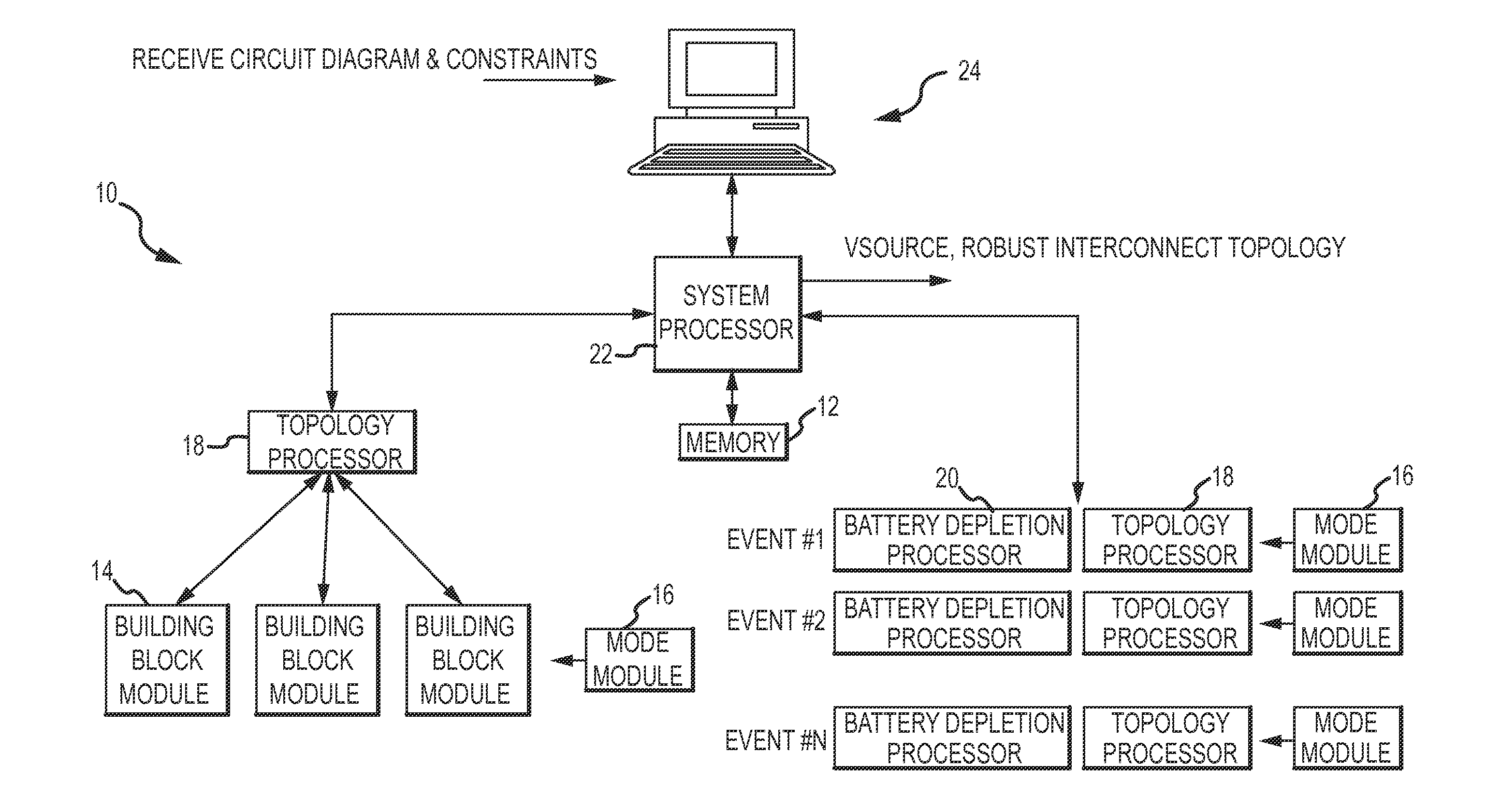
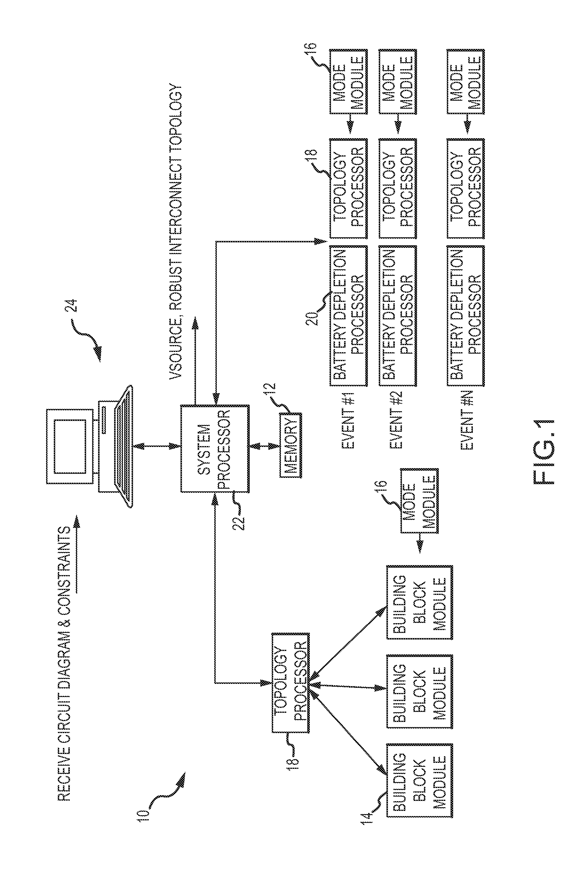
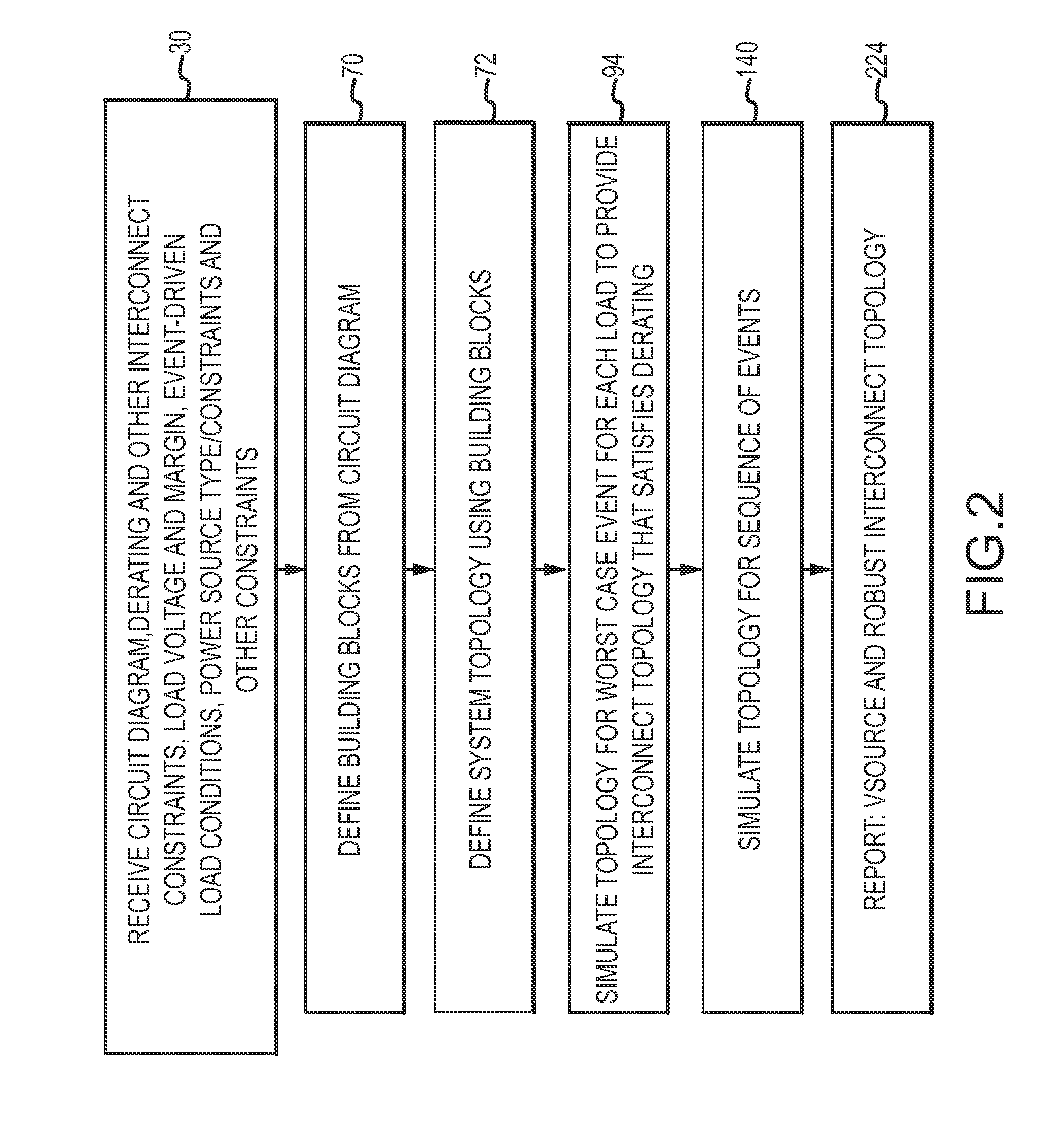
[0033]The present invention describes a systems power distribution tool that integrates the design of the power source and distribution network to provide a robust and balanced interconnect topology and power source. The tool may be configured to provide a minimal robust interconnect topology or minimal power source. The tool “pulls” load current from the source through interconnects to the loads. This allows the interconnects to be designed to satisfy derating conditions for worst case voltage and current conditions and the power source to be designed for actual conditions without margin stacking. The tool is implemented as a particular machine configured from one or more computing devices including memory and processors. The tool may be implemented using an application program such as Microsoft Excel®. The tool configures the application program and the computing devices to define a particular machine for performing power distribution analysis.

[0034]In reference to FIGS. 1-7, a ma...


PUM


Abstract

A systems power distribution tool integrates the design of the power source and distribution network to provide a robust interconnect topology and power source. This is accomplished with a machine of one or more computing devices configured as a systems power distribution tool. The tool “pulls” load current from the source through interconnects to the loads. This allows the interconnects to be designed to satisfy derating conditions for worst case voltage and current conditions and the power source to be designed to source the loads under actual conditions without margin stacking.

Description

GOVERNMENT RIGHTS[0001]This invention was made with United States Government support under Contract number W31P4Q-04-C-0059 with the Department of the Army. The United States Government has certain rights in this invention.BACKGROUND OF THE INVENTION[0002]1. Field of the Invention[0003]This invention relates to simulation modeling and analysis of power distribution in electrical systems and more particularly to a machine comprising one or more computing devices configured as a systems power distribution tool for use with event-driven systems that include a topology of power sources, resistive physical interconnects and event-driven fixed power loads.[0004]2. Description of the Related Art[0005]Electrical systems may be characterized as including a power source, electrical loads and a network of physical interconnects to distribute power from the source to the various loads. These systems may be static or single-event in which the load conditions are fixed throughout the timeline. Mo...

Claims


Application Information

Patent Timeline
IPC IPC(8): G06G7/50G06G7/62G06G7/66
CPCG06F17/5036G06F30/367
Inventor TIMMERHOFF, RICHARD L
Owner RAYTHEON CO
Why Eureka
Try Eureka