Piezoelectric device

Inactive Publication Date: 2011-06-09
SEIKO EPSON CORP
View PDF14 Cites 11 Cited by
  • Summary
  • Abstract
  • Description
  • Claims
  • Application Information

AI Technical Summary

Benefits of technology

[0016]In one embodiment, in a width direction of the piezoelectric vibrating reed, the vibrating part is provided to be located nearer the longer second supporting arm than the shorter first supporting arm. Thereby, the position of the center of gravity of the piezoelectric vibrating reed is nearer the second supporting arm than the first supporting arm, and the piezoelectric vibrating reed may be supported with more balance and the vibration leakage of the piezoelectric vibrating reed may effectively be prevented and more stability of vibration may be realized.
[0017]Further, in another embodiment, the base is formed in a box shape by a laminated structure of plural insulating material plates, the bottom surface of the cavity is defined by a first insulating material plate and the convex part is defined by a second insulating material plate laminated on the first insulating material plate, and the sealing hole is formed to have a step inside thereof by a larger hole part formed in the first insulating material plate and a smaller hole part formed in the second insulating material plate continuously to the larger hole part. As described above, the base having the sealing hole with the step for placement of a spherical-shaped or the pellet-shaped sealing material may have a laminated structure of two insulating material plates at the minimum, and there is an advantage for making the package smaller in height.
[0018]In still another embodiment, the lid has the convex part and the sealing hole of the convex part has a tilted surface tapered from an outer surface of the lid toward the cavity, and thereby, similarly, the spherical-shaped or the pellet-shaped sealing material to be heated and melted by irradiation with a laser beam, a halogen lamp, or the like may be placed on the tilted surface of the sealing hole so as not to be dropped into the cavity.
[0019]In yet another embodiment, the vibrating part includes a tuning-fork piezoelectric vibrating reed having at least a pair of vibrating arms that extend from the base end part in parallel and flexurally vibrate. In this case, since the vibrating arms has wider weight parts on their leading ends, even when the vibrating arms are made shorter, generation of the higher-order vibration may be suppressed and stability of the vibration frequency may be obtained, and thus, the entire piezoelectric vibrating reed may be made smaller in the longitudinal direction.
[0021]Further, in further another embodiment, the piezoelectric vibrating reed may be fixed not only to the first and second supporting arms but also to the bottom surface of the cavity in the base end part, and may be supported more stably and reliably.

Problems solved by technology

Further, smaller and thinner piezoelectric devices are demanded as recent electric equipment becomes smaller and thinner.
Accordingly, it is difficult to make the package thinner and shorter in height.
Similarly, in the case where the sealing hole is provided in the lid, a gap should be provided between the convex part of the lid inner surface and the piezoelectric vibrating reed, and thinning and shortening of the package are limited.

Method used


Image

  • Piezoelectric device
  • Piezoelectric device
  • Piezoelectric device

Examples


Embodiment Construction

[0027]Hereinafter, preferred working examples of the invention will be described with reference to the accompanying drawings.

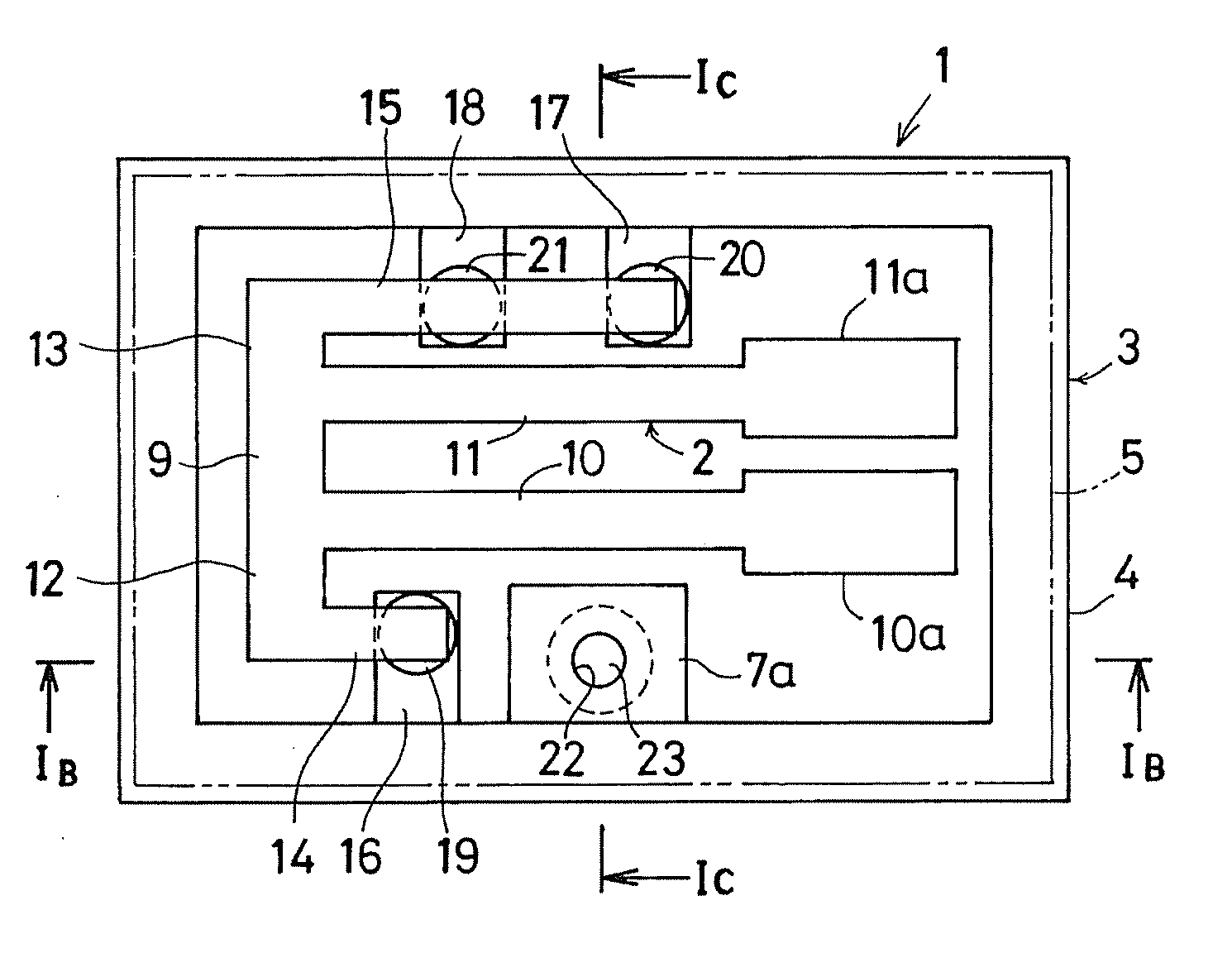
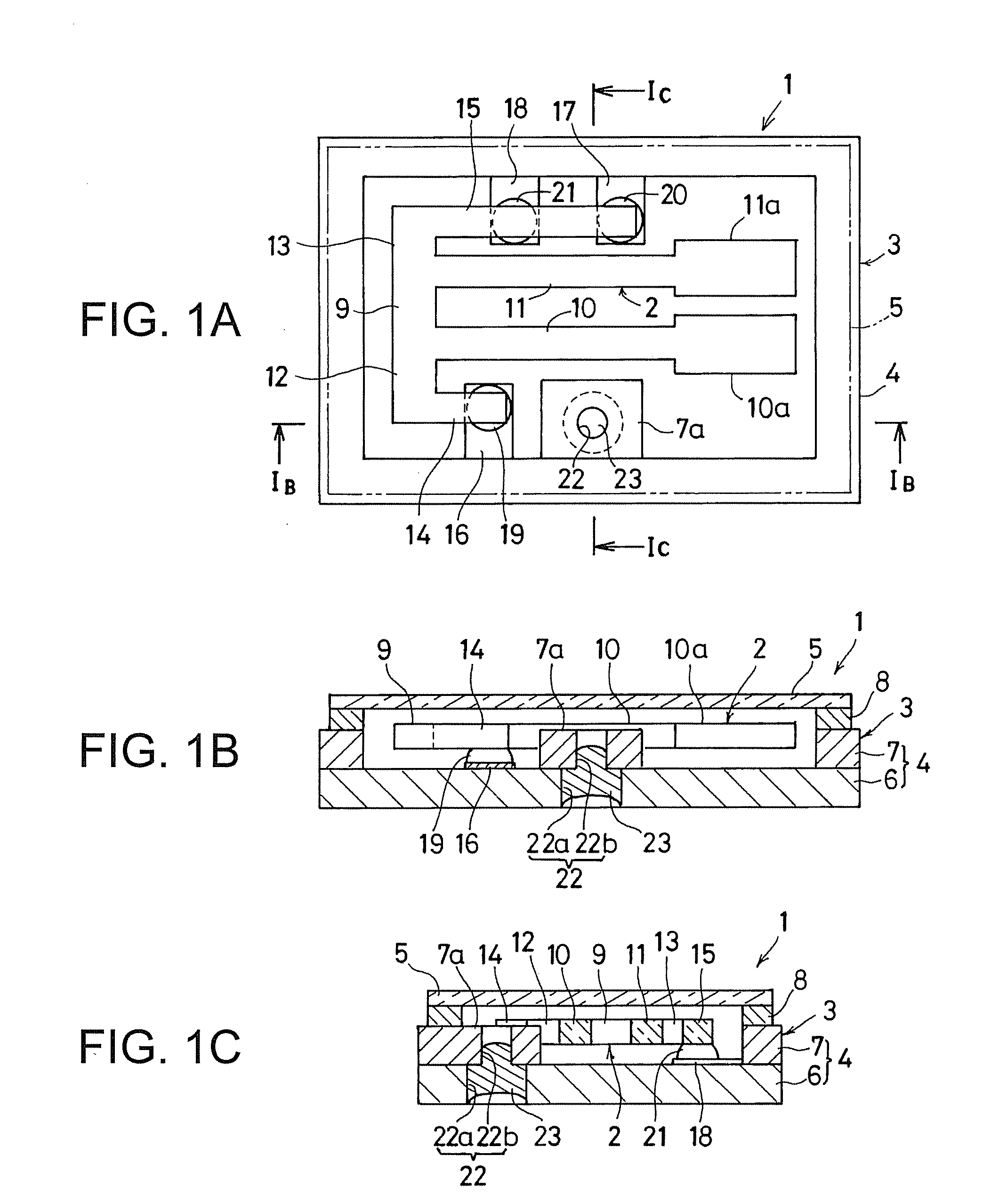
[0028]FIGS. 1A to 1C show a first working example of a piezoelectric device according to an embodiment of the invention. A piezoelectric vibrator 1 of the first working example includes a package 3 that air-tightly seals a tuning-fork piezoelectric vibrating reed 2 inside. The package 3 has a box-shaped base 4 of a ceramic material and a lid 5 of a flat rectangular thin plate. In the base 4, a cavity for holding the piezoelectric vibrating reed 2 inside is defined by laminating a lower ceramics thin plate 6 shaped in a rectangular flat plate and an upper ceramics thin plate 7 shaped in a rectangular frame. The lid 5 is air-tightly joined to the upper end surface of the base 4 by a sealing material 8.

[0029]The lid 5 is formed by a metal material such as kovar, alloy 42, or SUS, or an insulating material such as glass, silicon, quartz, or ceramic. In the case wh...


PUM


Abstract

A piezoelectric device includes: a piezoelectric vibrating reed; and a package, wherein the piezoelectric vibrating reed has a vibrating part and first and second supporting arms extending from a base end part, the package has a base, a lid, a cavity defined by the base and the lid, a convex part projecting from the base or the lid into the cavity, a length of the first supporting arm is shorter than a length of the second supporting arm, and the convex part is provided in a range ahead of a leading end of the first vibrating arm in an extension direction of the first supporting arm and at least partially overlapping with the second supporting arm in a length direction of the piezoelectric vibrating reed so as not to overlap with the piezoelectric vibrating reed in a plan view.

Description

BACKGROUND[0001]1. Technical Field[0002]The present invention relates to a piezoelectric device such as a piezoelectric vibrator or a piezoelectric oscillator used for various kinds of electronic equipment, and specifically, to a surface-mount piezoelectric device that air-tightly seals a package accommodating a piezoelectric vibrating reed.[0003]2. Related Art[0004]In related art, as piezoelectric devices, many surface-mount piezoelectric devices suitable for mounting on a circuit board or the like have been used. Generally, a surface-mount piezoelectric device includes a box-shaped thin base made of an insulating material such as ceramic or the like, and a flat plate-like lid joined thereto, and employs a package structure for mounting and air-tightly sealing a piezoelectric vibrating reed inside. Further, smaller and thinner piezoelectric devices are demanded as recent electric equipment becomes smaller and thinner.[0005]To downsize the piezoelectric device, a tuning-fork piezoel...

Claims


Application Information

Patent Timeline
IPC IPC(8): H01L41/053
CPCH03H9/1021H03H9/21H03H9/1035H03B5/32G01C19/5607H01L41/053H01L41/107H03H9/19H01L2924/16195H03H9/15H10N30/40H10N30/88
Inventor ISHIKAWA, KATSUOHARA, AKITOSHI
Owner SEIKO EPSON CORP
Why Eureka
Try Eureka