
Sail and method of manufacture

a manufacturing method and sail technology, applied in the field of sails and methods of manufacture, can solve the problems of unbalanced sail materials, complex mold contour control, and inability to vary economically the yarn content or mixture from place to place in the sail as needed

Inactive Publication Date: 2001-07-17
KEIRE FRED AIVARS
View PDF14 Cites 11 Cited by
  • Summary
  • Abstract
  • Description
  • Claims
  • Application Information

AI Technical Summary

Benefits of technology

It has now been found that a novel sail material, a sail made from it, and a method of production for the sail material have been discovered which enable a sail maker to by-pass, in a novel manner, the separate scrim-fiber manufacturing step and scrim insertion step apart from the sailcloth manufacturing step. At the same time, fiber oriented, structural sail panels or panel components are produced of length suitable to span from clew to head, head to tack and tack to clew. These panels are made by weaving and with more balanced properties obtainable in few steps. Weaving produces in one step, the primary structure and incorporates in the primary structure fill yarns as the secondary structure. The secondary structure can also be varied, e.g., of yarn content and / or yarn diversity. The panels which can be woven in this manner can be woven of considerable length and of suitable sizes for small boats from 6 ft. on a sail hoist as well as off-shore racing boats and one-design boats up to the America's Cup size sailboat sails and boats with a sail hoist up to 150 ft. Further, these panel materials have the necessary strength associated with the secondary structure typically introduced by the prior art by the separate scrim production and scrim insertion step. Additionally, the more balanced sail material properties may be improved still further by a balanced additions of supplemental materials such as X-Ply materials.
Further, the invention resides, in part, in elimination of the separate scrim insertion step of the prior art but does not exclude it from panel formation stage of load path specific panels. These advantages are achieved by using a weaving step in the formation of the primary and secondary load path specific panels. The method contributes the following benefits to the sail material, namely, each panel has a better stabilized load path primary and secondary yarns which can be locked in an improved load path grid with the secondary fill yarns as a result of the weaving. The formed panel has an improved, that is, less anisotropic and hence predictable properties with reduced bias distortion. The X-Ply material addition is further more balanced (from that achieved when adding to a 90 degree woven material) thus resulting in better balanced properties. Very little crimp is introduced in the primary structural warp yarns by the scrim like structure of the material. At the same time, such panel formation is amenable of a continuous or "step-an-index" panel formation. The weaving is by continuous shape adjustments of the warp yarns in the panel during its weaving stage. Other benefits result from a better lamination of the primary and secondary yarn structure and optional facile insertion of an X-ply material without sacrifice of the production rate. The novel woven structural sails have a beneficial strength-to-weight ratio, the thread line benefits of the structural sails, i.e., fiber oriented sails, have less of the manufacturing problems associated with the molded structural sails such as 3DL.TM. sails and can readily incorporate any of the novel yarns and fill materials appearing on the market.
In the manufacturing process, that is during weaving, the yarns may be set up once and continuous step-and-index operation repeatedly carried out without the requirement of a repeated set up as in the North Sails process. The structural sails and the panels as these are produced for the sails can be tailored to meet any recognized or general structural shortcomings in a particular panel. Each sail can be designed in the panel manufacturing process to have certain performance, weight-to-strength ratio, horizontal and vertical curve configuration (when in use), or boundary point reinforcement features. The process is of exceptional advantage in serial mass production of same size panels.

Problems solved by technology

Neither process inserts a scrim between the fibers and bottom film, thereby resulting in an unbalanced sail material.
While each of the prior art methods has its benefits and short comings, the separate layering of the scrim on top of the primary structural fiber members on a mold introduces additional problems such as sufficient temperature and pressure for laminating, conforming of the film to the structure, and adhesion of the film material to the structure.
In the 3DL.TM. method disclosed in U.S. Pat. No. 5,097,784 besides the above inability to laminate a scrim between the bottom film and fibers, the complexity resides in the mold contour control, the pre-shaping of the film and scrim in panels which then must be placed on the mold, and the inability to vary economically the yarn content or mixture from place to place in the sail as needed and the complexity in the fiber orientation to produce an approximation of the primary and secondary load paths.

Method used


Image

  • Sail and method of manufacture
  • Sail and method of manufacture
  • Sail and method of manufacture

Examples


Embodiment Construction

With reference to the drawings schematically illustrating various embodiments of the invention and without limiting other aspects of the invention:

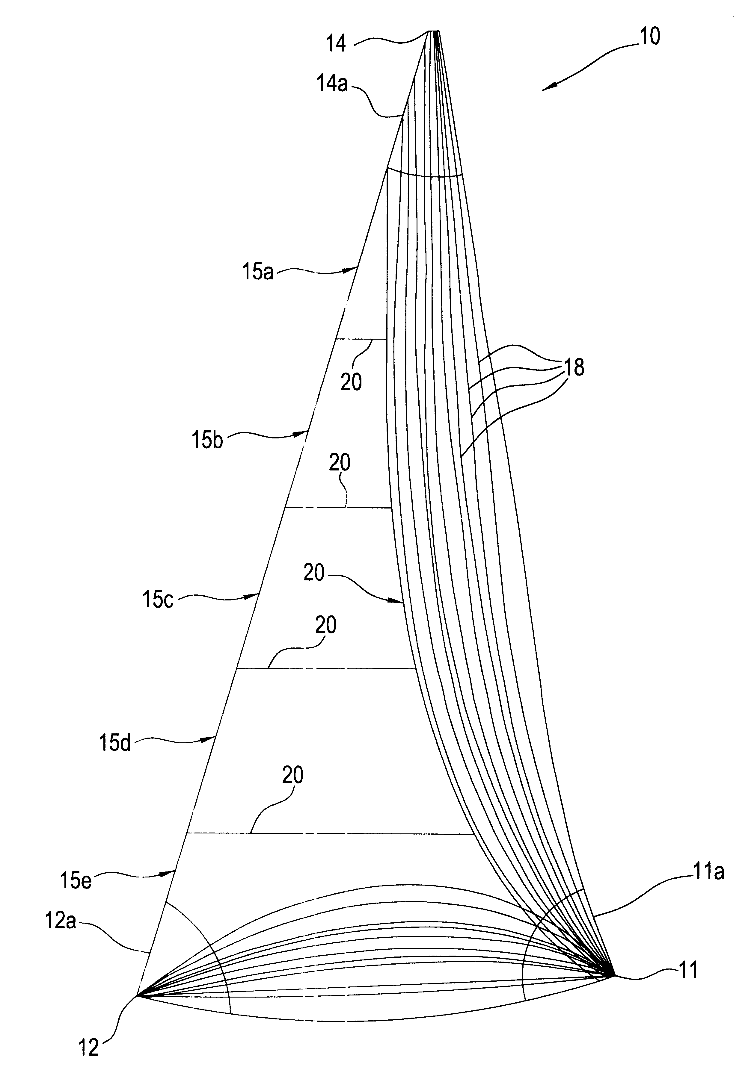
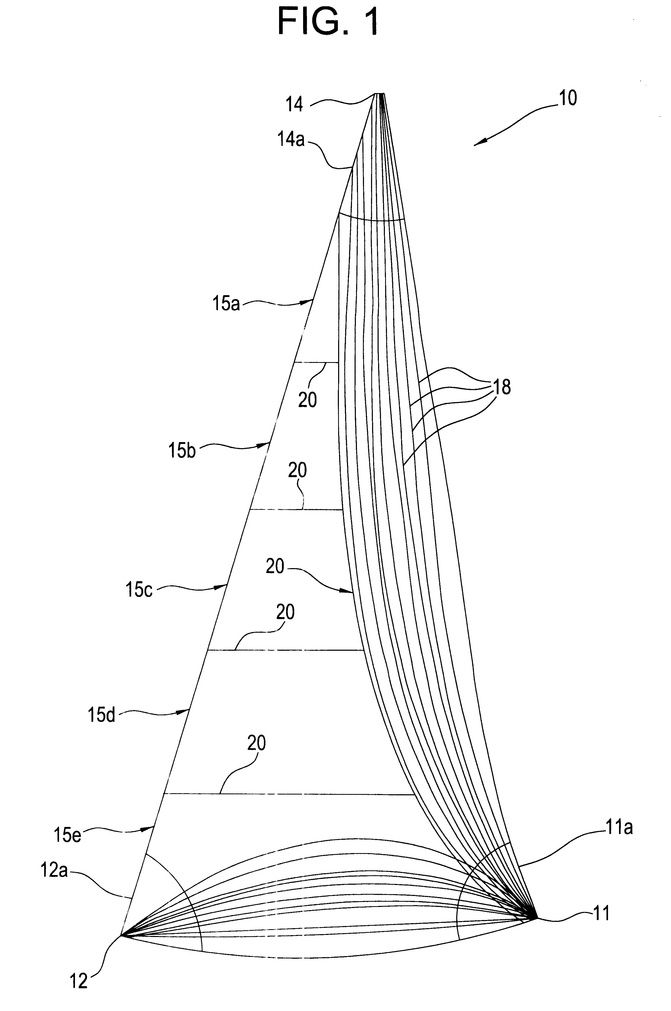
FIG. 1 illustrates, in a plan view, a jib or genoa sail according to the invention herein;

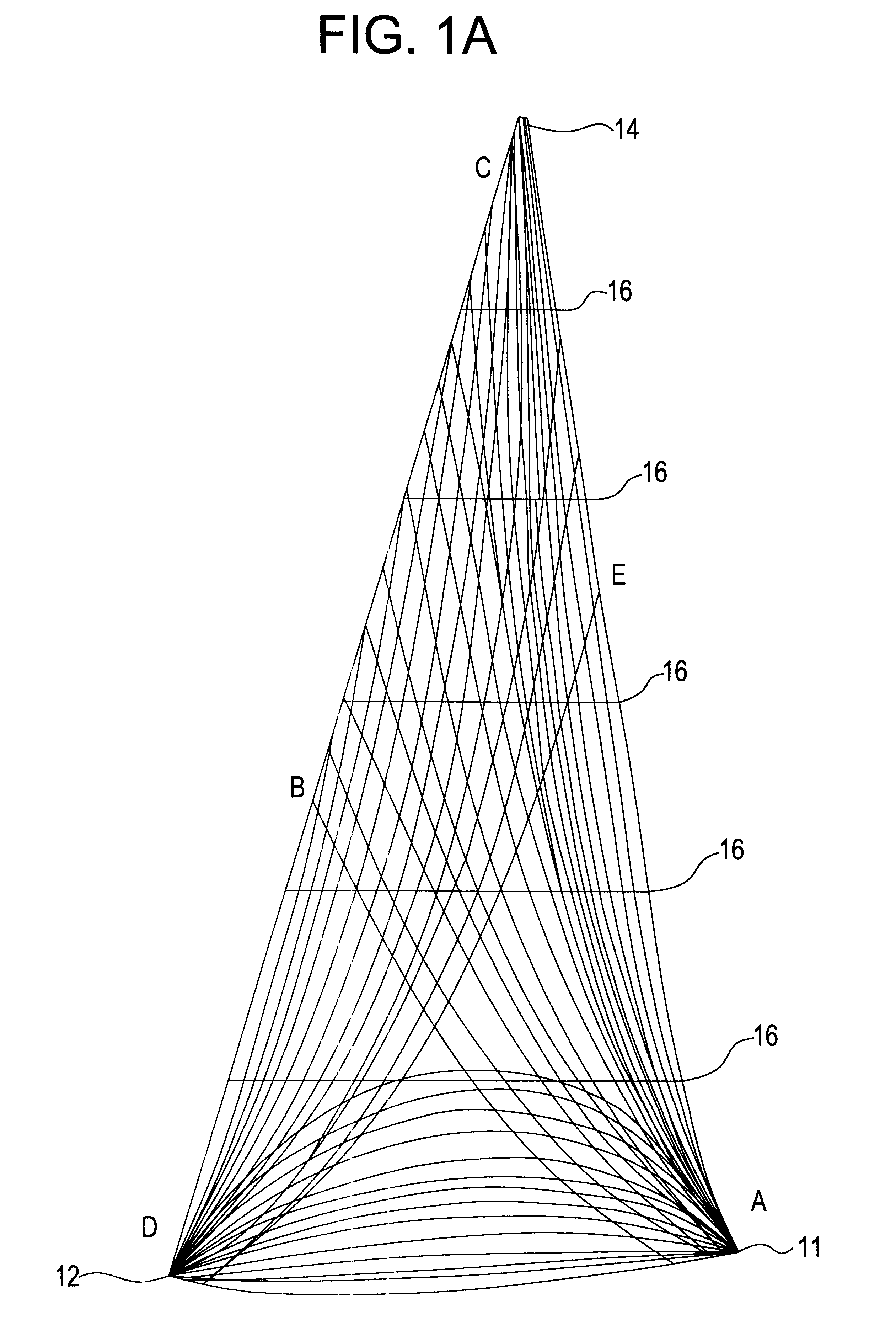
FIG. 1a illustrates, in plan view, a jib sail of another embodiment with panels made according to the invention herein;

FIG. 2 illustrates, in a plan view a mainsail according to the invention herein;

FIG. 3 illustrates schematically, in a cross-sectional view, a weaving loom for the sail material according to the invention herein including attendant yarn-feed means, a resin application section, and a laminating section for carrying out various aspects of the herein described invention as shown in FIGS. 1, 1a, and 2;

FIG. 3a, illustrates in a top view, a yarn gathering device used in FIG. 3 loom for making corner panels for the sail shown in FIG. 1;

FIG. 4 illustrates, in a perspective view, a laterally adjustable heddle segment, including top and bottom...


PUM

PropertyMeasurementUnit
sizesaaaaaaaaaa
sizeaaaaaaaaaa
modulusaaaaaaaaaa

Abstract

Fiber oriented sails made of woven panels of scrim type weave wherein warp yarns in the panels follow primary load paths in a sail and a method for making woven panels.

Description

This invention relates to sails for sail driven vessels including sail assisted vessels; more particularly, this invention relates to novel sails, novel materials for sails, and the method for production of sail materials and sails. This application is related to my concurrently filed application Ser. No. 09 / 521,446, now allowed.BACKGROUND FOR THE INVENTIONIn chronological order in the past century, sails have been made of woven textile materials. Base fibers for these textile materials were derived from natural polymers, i.e., cellulose, of which cotton and linen were preeminent. In general, the fibers in these textile yarns used for weaving sailcloth were of short length as it is typically found in natural polymers. However, significant advantage in sails was realized by longer length fibers and high quality sails were sold as being made of long length "Egyptian cotton" yarns.With the advent of synthetic fibers, that is an extruded bundle of "continuous" filaments for yarns, the l...

Claims


Application Information

Patent Timeline
Patent Type & Authority Patents(United States)
IPC IPC(8): B63H9/06B63H9/00
CPCB63H9/0657Y10T428/24091Y10S428/902B63H2009/0678B63H9/067B63H9/0678Y10T442/102
Inventor KEIRE, FRED AIVARS
Owner KEIRE FRED AIVARS
Learn More