
Method For Estimating Distance Between Transmitter and Receiver, and Transmitter and Receiver Implementing Same

Inactive Publication Date: 2008-11-27
ESSENSIUM
View PDF3 Cites 9 Cited by
  • Summary
  • Abstract
  • Description
  • Claims
  • Application Information

AI Technical Summary

Benefits of technology

[0010]It is an aim of the present invention to provide a method for estimating the distance between a transmitter and a receiver, with which the need for separate radio-transceiver devices for the communications and ranging signals can be avoided.
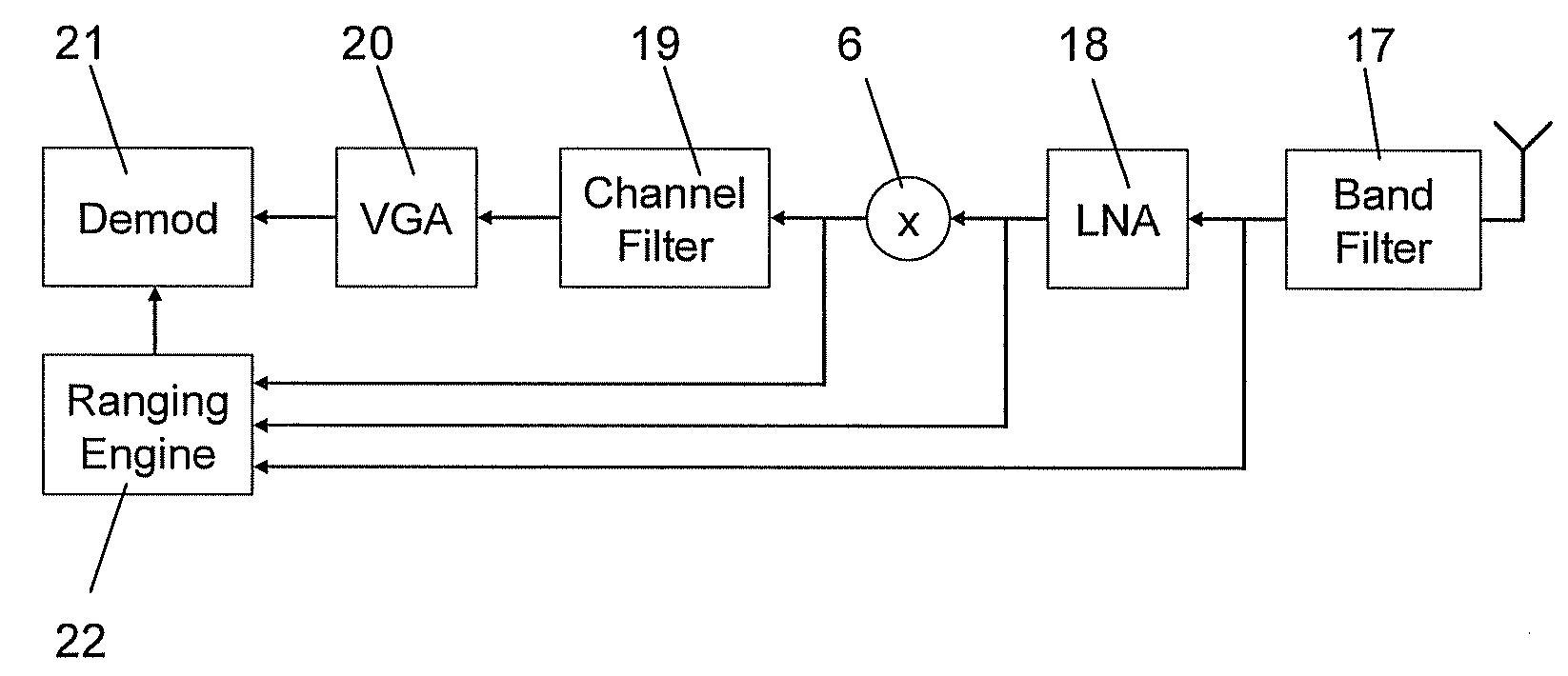
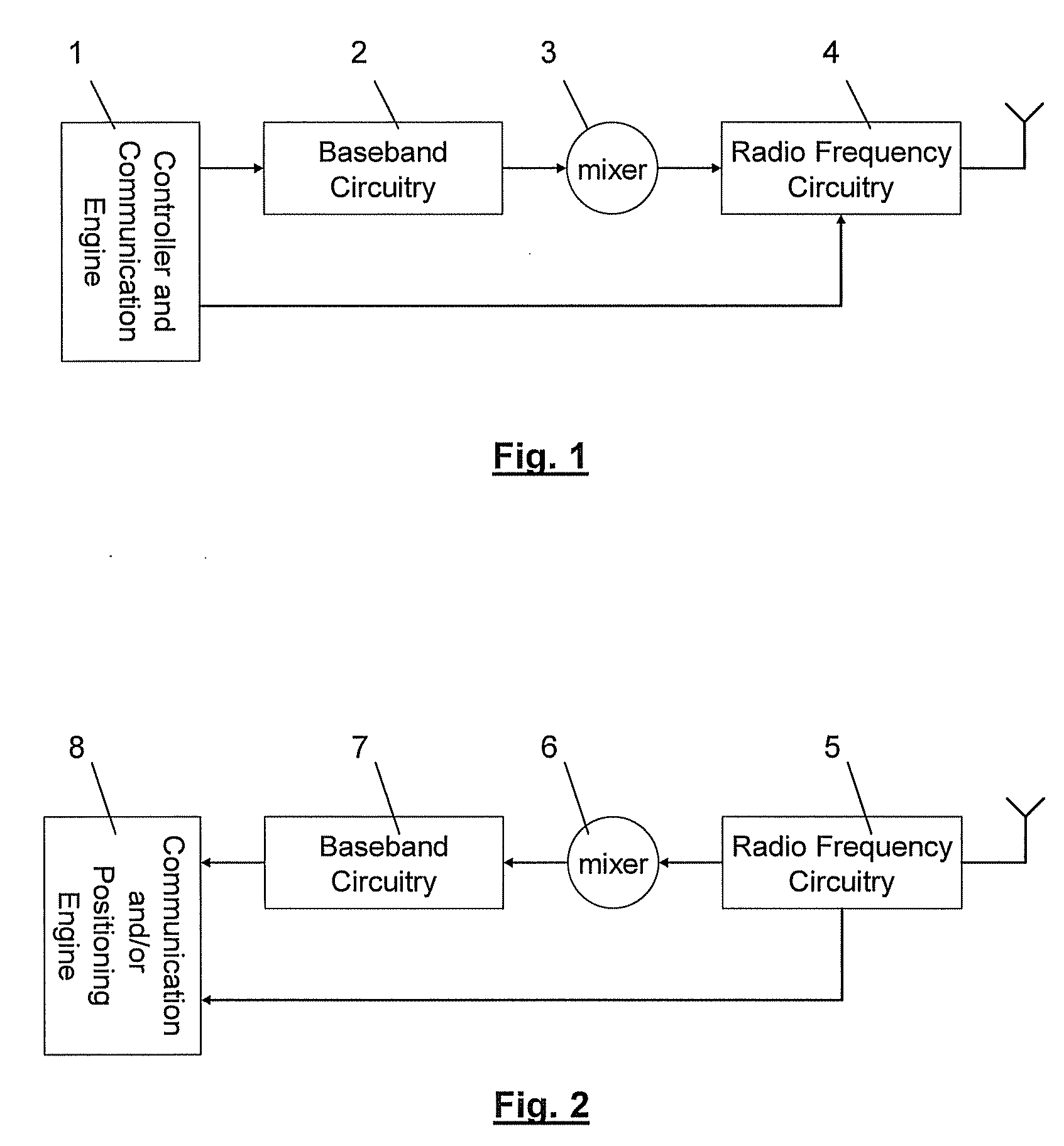
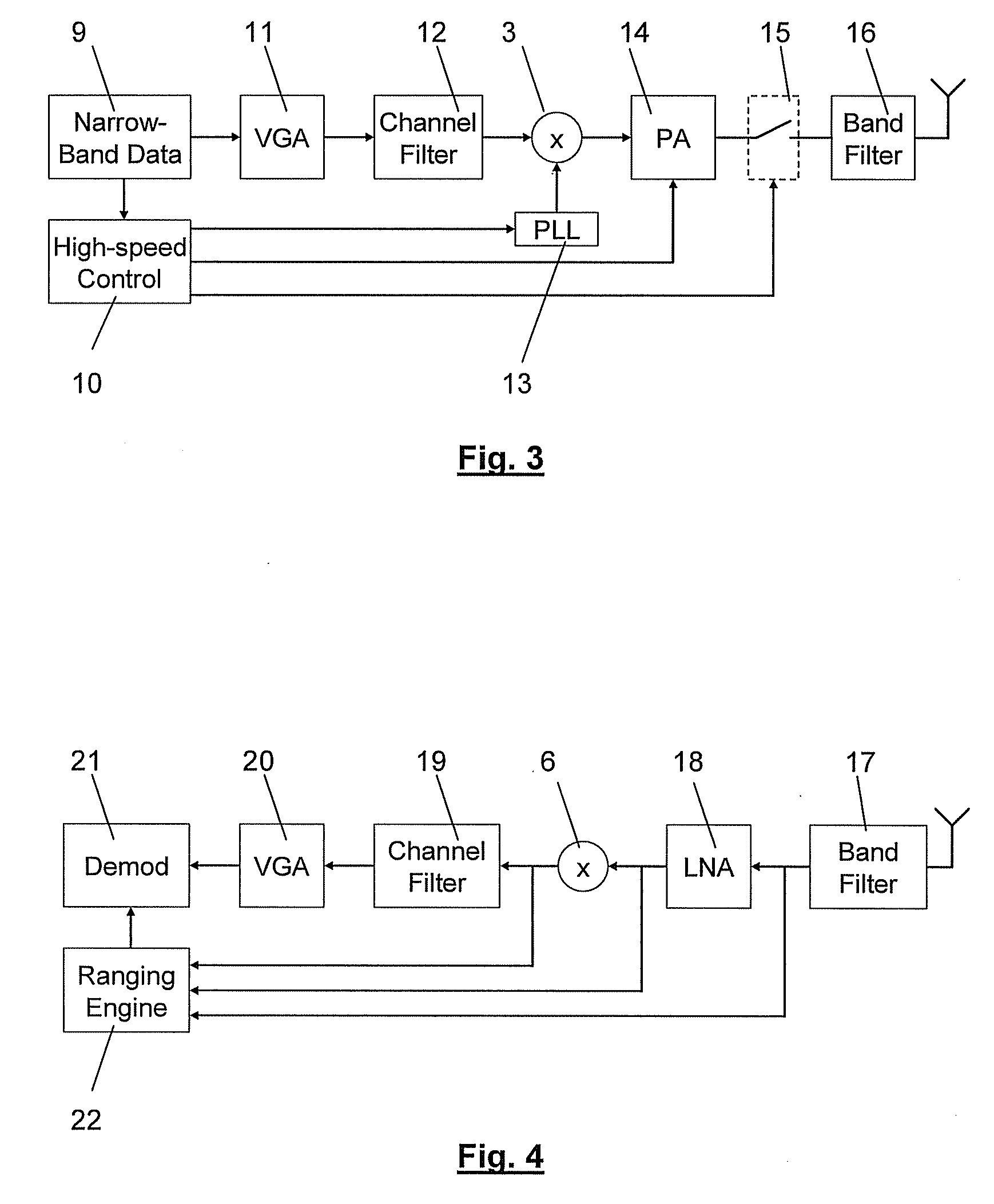
[0016]According to the invention, the second bandwidth of the ranging component encompasses the first bandwidth of the first type of signals, which means that the first signals are transmitted in a portion of the bandwidth which is used for the ranging component. This makes it possible to use the same radio transceiver device for transmitting / receiving both types of signals. More particularly, a part of the radio transceiver circuitry, which is actually designed for the first signals within the first bandwidth, can now be used for also transmitting the ranging component, for example by manipulating some of its control ports using high-speed. In other words, this invention allows upgrading existing systems designed for wireless communication with an accurate ranging capability by exploiting the fact that at least part of the transceiver circuitry is capable of transmitting signals with a wider bandwidth.
[0019]The first signal type may for example comprise pure communication signals, whereas the second signal type may comprise a composite signal with a communication component next to the ranging component. For communication, a relatively narrow bandwidth is desirable in view of simplicity, power-efficiency and communication range (more narrow communication bands and availability of unlicensed spectrum at relatively low center frequencies). For ranging (being estimation of the distance between transmitter and receiver, or more in general between a transmitter and multiple receivers) wider bandwidths have more attractive properties in view of a finer temporal resolution which allows to separate between the distinct multi-path components, whereas for narrower bandwidths the temporal waveforms are smeared and hence provide poor resolution. As a result it is desirable that the second bandwidth exceeds the first bandwidth.

Problems solved by technology

While these techniques have adequate performance outdoors and when a sufficiently strong line-of-sight signal is available, they suffer low accuracy in indoor environment.
The key reason for this performance degradation is the higher number of reflections and often obstructed line-of-sight path, aka multi-path propagation, which complicates the estimation of the so-called time-of-arrival and hence time-of-flight of the transmitted signal.
Especially due to the narrow-band nature of the transmitted signals, these copies have a wide span in the time-domain and hence tend to overlap.
As a result, copies having travelled several meters more than the line-of-sight path can typically not be separated from the latter by the receiver and induce errors in the position estimate of the same order of magnitude.
However, ultra-wideband signalling has serious disadvantages with respect to classical narrowband communication when it comes to the link budget.
Specifically, the signal-to-noise ratio at the receiver gets proportionally worse as the bandwidth increases, due to the increased in-band noise bandwidth.
Due to this, and also the high carrier frequency at which ultra-wideband communication usually takes place, due to regulatory constraints, the power consumption of such system tends to be significantly higher than that of classical narrowband systems.
Firstly, they need fully separated radio-transceiver devices for transmitting and receiving the narrowband communications and wide-band ranging signals.
Secondly, the signalling happens in distinct frequency bands.
Thirdly, the ranging transmissions are in no way backward compatible to the existing means of narrowband communications on top of which they are implemented.

Method used


Image

  • Method For Estimating Distance Between Transmitter and Receiver, and Transmitter and Receiver Implementing Same
  • Method For Estimating Distance Between Transmitter and Receiver, and Transmitter and Receiver Implementing Same
  • Method For Estimating Distance Between Transmitter and Receiver, and Transmitter and Receiver Implementing Same

Examples


Embodiment Construction

[0033]The present invention will be described with respect to particular embodiments and with reference to certain drawings but the invention is not limited thereto but only by the claims. The drawings described are only schematic and are non-limiting. In the drawings, the size of some of the elements may be exaggerated and not drawn on scale for illustrative purposes. The dimensions and the relative dimensions do not correspond to actual reductions to practice of the invention.

[0034]Furthermore, the terms first, second, third and the like in the description and in the claims, are used for distinguishing between similar elements and not necessarily for describing a sequential or chronological order. The terms are interchangeable under appropriate circumstances and the embodiments of the invention can operate in other sequences than described or illustrated herein.

[0035]Moreover, the terms top, bottom, over, under and the like in the description and the claims are used for descriptiv...


PUM


Abstract

A method for estimating the distance between a transmitter and at least one receiver. The transmitter has radio transmission circuitry, at least part of which is operable in a first operation mode for transmitting a first signal type within a first bandwidth and in a second operation mode for transmitting a second signal type including at least a ranging component which occupies a second bandwidth which encompasses and exceeds the first bandwidth. The method includes the steps of: (i) operating part of the radio transmission circuitry in a second operation mode, (ii) transmitting a signal of a second signal type, (iii) receiving a signal on one receiver and (iv) estimating the distance between the transmitter and a receiver from the ranging component in each received signal. A suitable transmitter and receiver for implementing the method are described.

Description

CROSS REFERENCE TO RELATED APPLICATIONS[0001]This application is the entry into the United States of PCT Application Number PCT / EP2006 / 070040 filed Dec. 20, 2006 and claims priority from European Patent Application Number EP / 05112981.5 filed Dec. 23, 2005, the entirety of each of which are hereby incorporated by reference.BACKGROUND OF INVENTION[0002]1. Technical Field[0003]The present invention relates to a method for estimating the distance (also referred to as range) between a transmitter and a receiver, and to a transmitter and a receiver in which the method is implemented.[0004]2. Background Art[0005]Position determination is an important feature for many applications of wireless networks. It has been proposed either as an additional feature to add value to wireless communication networks (such as enhanced routing or ease in installation for wireless sensor networks) or as a stand-alone feature when location awareness is a goal in itself (such as asset or person tracking applic...

Claims


Application Information

Patent Timeline
IPC IPC(8): G01S11/00
CPCG01S5/06G01S11/08G01S13/767
Inventor VANDENAMEELE, PATRICK
Owner ESSENSIUM
Learn More