Protective Electrical Wiring Device with a Center Nightlight

a technology of electrical wiring and nightlights, applied in the direction of coupling device connections, emergency protective arrangements for limiting excess voltage/current, etc., can solve the problems of electrical connectivity breakage, fire, shock or electrocution, certain types of faults known to occur in branch electric circuits and electrical wiring systems

Inactive Publication Date: 2009-02-05
PASS SEYMOUR
View PDF16 Cites 25 Cited by
  • Summary
  • Abstract
  • Description
  • Claims
  • Application Information

AI Technical Summary

Benefits of technology

[0014]The present invention addresses the needs described above by providing an electrical wiring device that includes a light source that is both adapted to a wiring device form factor and configured to address the drawbacks and needs described above. The wiring device of the present invention may be configured to address both safety issues, i.e., electrical fault conditions as well as ambient lighting issues.

Problems solved by technology

Certain types of faults are known to occur in branch electric circuits and electrical wiring systems.
These faults represent serious safety issues that may result in fire, shock or electrocution if not addressed properly.
The circuit interrupter provides power to the load terminals under normal conditions, but breaks electrical connectivity when the protective device detects a fault condition in the load circuit.
Another safety issue that is of great concern relates to the amount of ambient lighting in a given room or space.
On the other hand, the darkened room represents a safety issue.
For example, if an object is disposed relatively low to the floor surface the person may trip over it and suffer an injury.
There are situations where a light switch is not available, or is not readily available.
A person entering a darkened theatre would expect to incur the wrath of his fellow patrons if he turned the theatre lights ON while finding a seat.
The most obvious drawback in getting the portable nightlight into a socket in a darkened room is finding the socket in the first place.
On the other hand, once the night light is inserted into the receptacle, it may remain there day and night for an extended period of time and represent a waste of energy.
Unfortunately, the resident may forget to plug the light back into the socket until after night fall and finds himself revisiting the darkened room scenario.
In addition, once a small night light is unplugged from the receptacle there is the possibility that it will become lost, misplaced, or damaged from excessive handling.
While this approach obviates some of the drawbacks described above, there are other drawbacks that come into play.
Conventional permanent lighting elements such as incandescent and neon lights have a relatively short life expectancy of only a few years and, therefore, require periodic servicing and / or replacement.
This problem is exacerbated by the fact that the light is typically hard-wired to power contacts disposed in the wiring device.
As such, the light element is permanently ON, further limiting the light elements life expectancy of the device.
One design problem associated with using a light sensor to selectively actuate the light element relates to providing a proper degree of isolation between the light sensor and the light element.
Accordingly, conventional devices of this type often fail to provide an adequate amount of illumination for the intended application and, therefore, do not address the safety concern in a satisfactory manner.

Method used


Image

  • Protective Electrical Wiring Device with a Center Nightlight
  • Protective Electrical Wiring Device with a Center Nightlight
  • Protective Electrical Wiring Device with a Center Nightlight

Examples


first embodiment

[0051]As embodied herein and depicted in FIG. 4, a perspective view of the shutter assembly optionally employed in the present invention is shown. Reference is made to U.S. patent application Ser. Nos. 10 / 729,685, 10 / 900,778, and 11 / 609,793, which are incorporated herein by reference as though fully set forth in its entirety, for a more detailed explanation of various embodiments of the protective shutter assembly 18. The shutter assembly may be optionally employed in any of the embodiments disclosed herein.

[0052]When assembled, the upper shutter 190 is inserted into lower shutter 170 until stop members 1920 extend beyond rail guides 1782 and snap into place. This position represents the closed position, wherein the upper transverse structure 196 covers neutral aperture 174 (not shown) and upper base 198 covers hot aperture 176 (not shown). The lower shutter member 170 and the upper shutter member 190 are movable relative to each other from the closed position to the open position i...

second embodiment

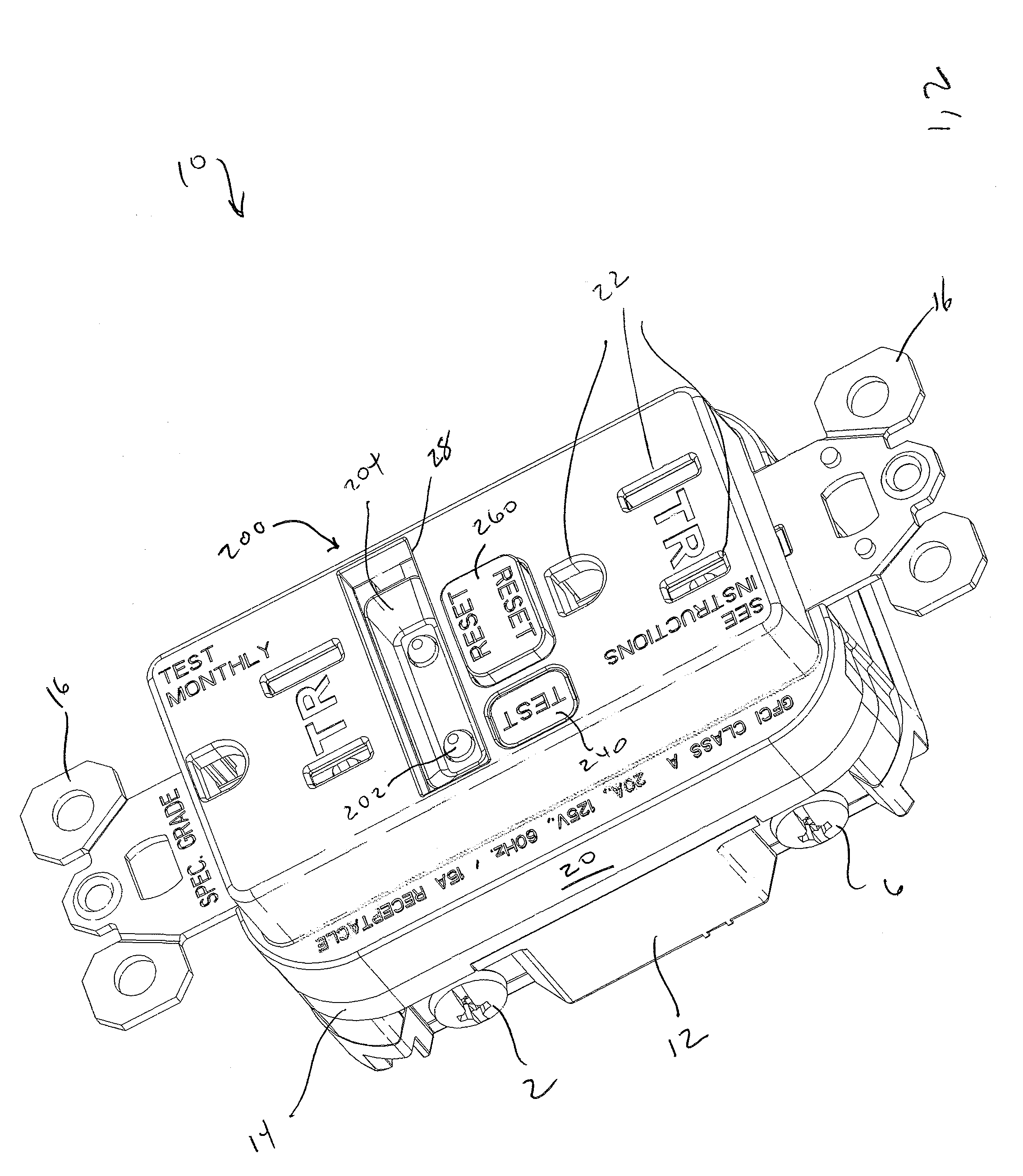
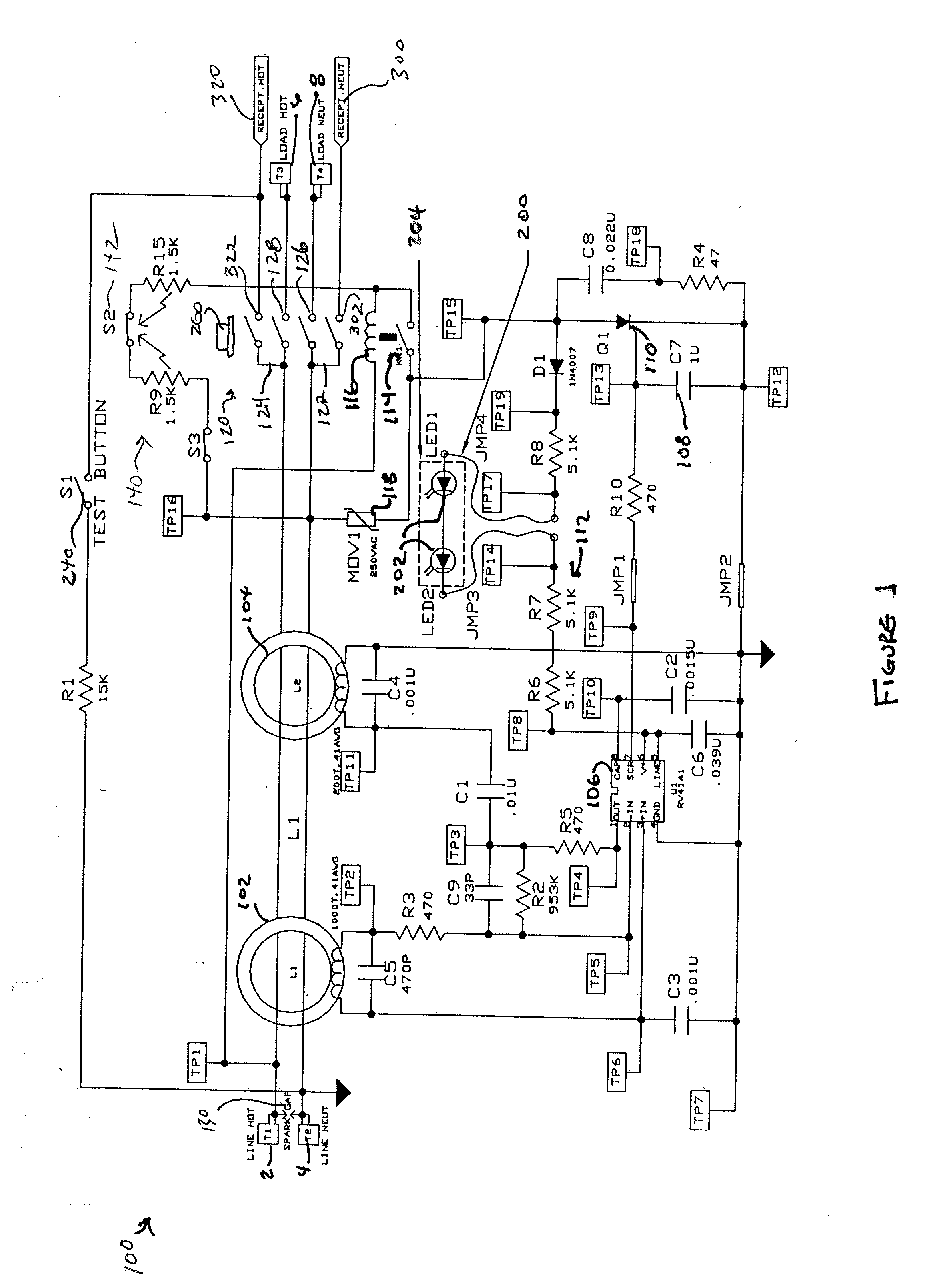
[0061]Referring to FIG. 8, a schematic of the center night light assembly 200 in accordance with the present invention is shown. As shown in FIG. 7, connection “B” is connected to the neutral receptacle terminal structure 30. The light assembly circuit 200 includes a current rectifying diode D1 in series with LEDs 202 and current limiting resistors R80, and R82. Comparing FIG. 7 and FIG. 8, it becomes apparent to those skilled in the art that the lighting assembly 200 again functions as a reset indicator. When the device is in the reset state, LEDs 202 are ON. When the device is tripped, the LEDs 202 are OFF.

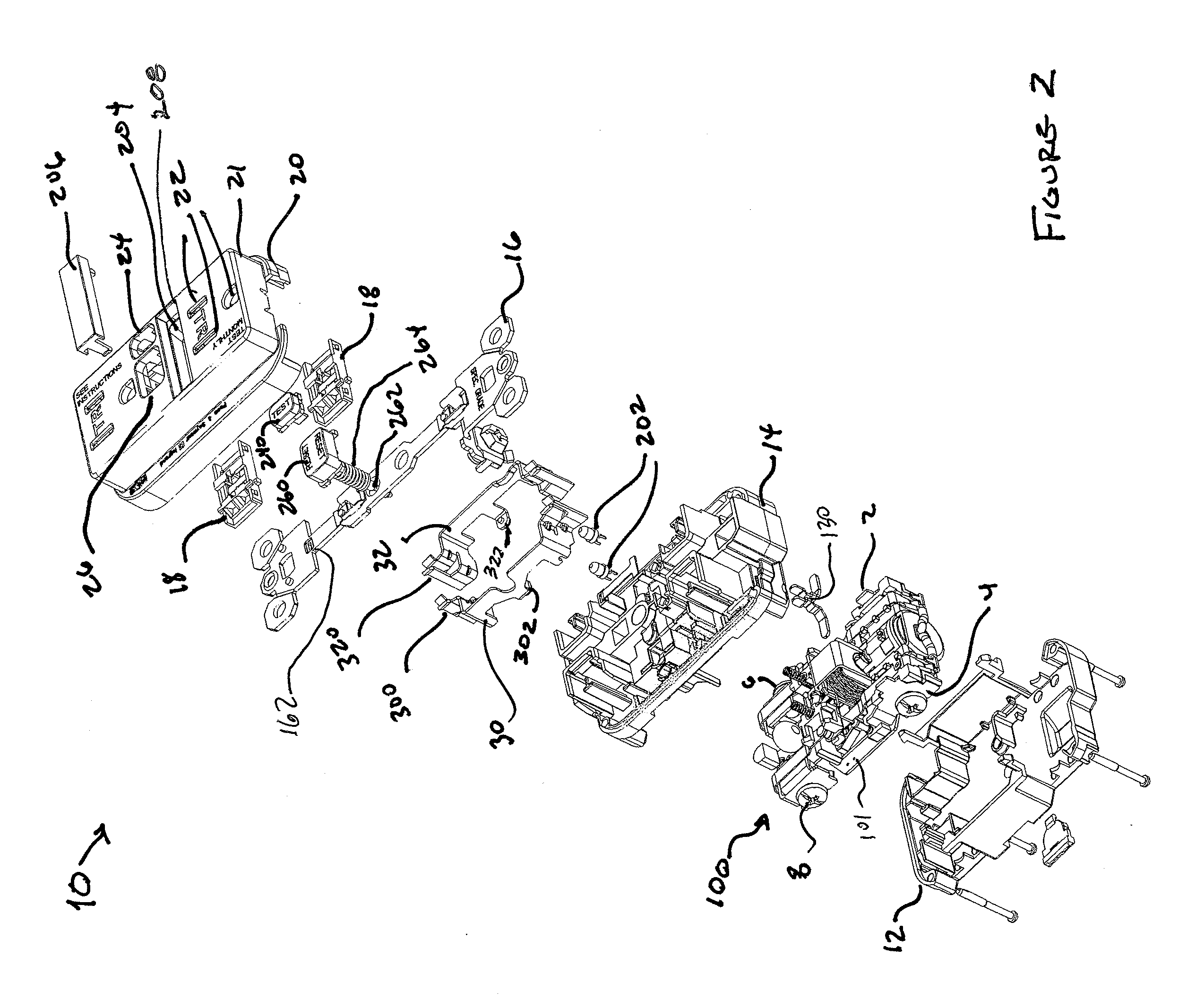
[0062]FIG. 9 is an exploded view of the second embodiment of the present invention previously discussed relative to FIGS. 7-8. FIG. 9 is very similar to the exploded view previously shown in FIG. 2. Accordingly, a description of like features is omitted for brevity's sake and only the differences are explained. In the second embodiment, lens 206 has a “U-shaped” cross section si...

third embodiment

[0064]The third embodiment includes an additional indicator 150 disposed in parallel with auxiliary switch 114. As noted above, the auxiliary switch 114 is configured to open when circuit interrupter 120 is in the tripped position. If SCR 110 is shorted, or is permanently ON, auxiliary switch 114 ensures that solenoid 116 is not permanently connected to a current source. Accordingly, if reset button 260 is activated, circuit interrupter 120 resets but immediately trips in response to the trip mechanism, which in turn moves auxiliary switch 114 to the open position before solenoid 116 is able to burn out. The indicator 150 is implemented as a trip indicator, emitting a visual and / or audible indicator signal when circuit interrupter 120 is in the tripped state, i.e., when the auxiliary switch 114 is open. The trip indicator LED 150, therefore, is energized when there is power on the line terminals and the circuit interrupter is in the tripped condition. The indicator 150 is OFF when d...


PUM


Abstract

The present invention is directed to a electrical wiring device that includes a housing having a plurality of line terminals and a plurality of load terminals, the plurality of load terminals including a plurality of receptacle terminals. A cover assembly is coupled to the housing. The cover assembly includes at least one set of receptacle openings disposed on either side of a central portion of the cover assembly. Each of the at least one set of receptacle openings is in communication with a portion of the plurality of receptacle terminals. A fault detection assembly is coupled to the plurality of line terminals. The fault detection circuit is configured to provide a fault detection output in response to detecting a fault condition. A circuit interrupter is coupled between the plurality of line terminals and the plurality of load terminals. The circuit interrupter includes a first set of contacts configured to provide at least one electrically continuous path between the plurality of line terminals and the plurality of load terminals in a reset state. The first set of contacts is configured to disconnect the at least one electrically continuous path in response to the fault detection output to thereby enter a tripped state. A light assembly is coupled to the plurality of line terminals or the plurality of load terminals. The light assembly has a light transmission region disposed in the central portion and occupying a substantial portion of a width of the cover assembly. The light assembly is selectively driven from a deenergized state to a light emitting state in response to a predetermined stimulus.

Description

CROSS-REFERENCE TO RELATED APPLICATIONS[0001]This is a continuation-in-part of U.S. patent application Ser. No. 11 / 609,793 filed on Dec. 12, 2006 and U.S. patent application Ser. No. 10 / 998,369 filed on Nov. 29, 2004, the content of which is relied upon and incorporated herein by reference in its entirety, and the benefit of priority under 35 U.S.C. §120 is hereby claimed, U.S. patent application Ser. No. 10 / 998,369 claims the benefit of priority under 35 U.S.C. § 119(e) to U.S. Provisional Patent Application Ser. No. 60 / 550,275, this application is also a continuation-in-part of U.S. patent application Ser. No. 11 / 294,167 filed on Dec. 5, 2005, which is a continuation-in-part of U.S. patent application Ser. No. 11 / 242,406 (Now U.S. Pat. No. 7,285,721) filed on Oct. 3, 2005, which is a continuation application of U.S. patent application Ser. No. 10 / 726,128 filed on Dec. 2, 2003 (now U.S. Pat. No. 6,989,489), the contents of which are relied upon and incorporated herein by reference ...

Claims


Application Information

Patent Timeline
Patent Type & Authority Applications(United States)
IPC IPC(8): H01R13/46
CPCH01R13/4534H01R13/652H01R13/7135H02H3/02H01R24/78H01R2103/00H01R13/7175
Inventor WEEKS, RICHARDRICHARDS, JEFFREY C.WILSON, GARY O.SAVICKI, JR., GERALD R.
Owner PASS SEYMOUR
Why Eureka
Try Eureka