Audio device and sound beam control method

Active Publication Date: 2009-02-05
YAMAHA CORP
View PDF16 Cites 16 Cited by
  • Summary
  • Abstract
  • Description
  • Claims
  • Application Information

AI Technical Summary

Benefits of technology

[0013]In the present invention, when the user of an audio device listens to the audio contents alone, it is possible to set up it so as to reduce leaked sound. While plural persons listen to the same audio contents, even when a specific person therein is distanced from a speaker array device, or even when a specific person therein is an aged person having poor hearing, it is possible to transmit sound to the specific person with a large sound volume (or a high sound pressure), and it is possible to transmit sound to the other persons with a normal sound volume and a normal sound quality.

Problems solved by technology

Accompanied with increasing population, housings have been concentrated in cities in particular; hence, there is a tendency that noise pollution increases not only with respect to inmate family members but with respect to surrounding people.
For example, when a viewer watches and listens to an audio-visual device (e.g., a television receiver) so as to generate a relatively large volume of sound in the night, noise pollution occurs which can cause annoyance for other persons other than the viewer.
Until now, a viewer may pay attention to avoid causing noise pollution to the neighboring persons by reducing sound volume; however, when sound volume is simply reduced, there is a disadvantage in that it may be difficult to hear the audio contents (or programs).
However, when a viewer at a surrounding position of the audio-visual device or a viewer having adequate hearing watches and listens to the same contents (or programs) together with the others, there is a problem in that discomfort may occur by the increasing sound volume.
In addition, increasing the sound volume may cause noise pollution with respect to inmate family members having no intention to watch and listen to the contents (or programs) and with respect to neighboring persons.
Thus, the cable and amplifier speaker may cause disturbance and are troublesome to set up.

Method used


Image

  • Audio device and sound beam control method
  • Audio device and sound beam control method
  • Audio device and sound beam control method

Examples


Embodiment Construction

(Explanation of Sound Beam)

[0036]An audio device according to a preferred embodiment of the present invention will be described with reference to the accompanied drawings. This audio device can be connected to an audio-visual device such as a television receiver, or the audio device can be used independently.

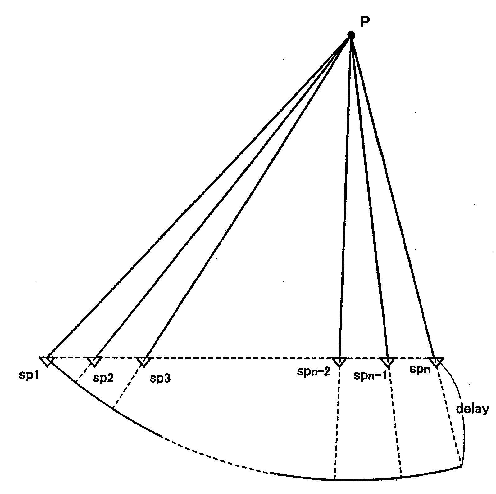
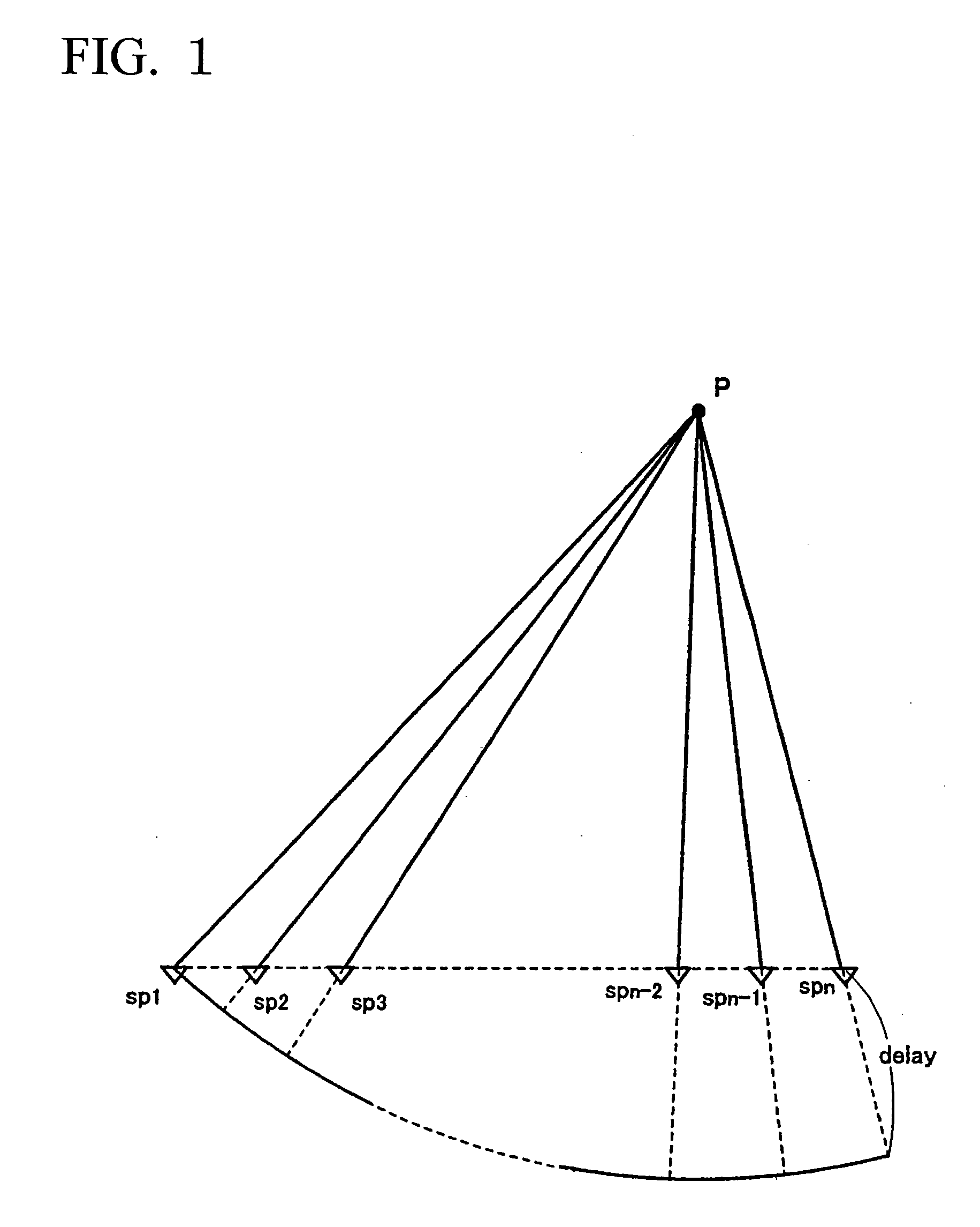
[0037]The audio device of the present invention is equipped with a speaker array device. FIG. 1 is a drawing for use in the explanation of a sound beam forming method using the speaker array device. The speaker array device is an alignment of plural speaker units in a horizontal direction. Suppose that the speaker array device is formed by aligning forty small-size speakers in three lines (which can be retrieved via the Internet: URL: http: / / www.yamaha.co.jp / news / 2004 / 04111601.html), for example. Each of the speaker units is supplied with the same audio signal, whereas the supply timing and sound volume can be independently controlled with respect to each speaker unit. The outpu...


PUM


Abstract

In an audio device equipped with a speaker array device aligning a plurality of speaker units, a sound beam is emitted towards a specific person in a main beam direction, thus realizing the listening of the audio contents with good sound quality. Other persons listen to the audio contents at off-beam positions; hence, leaked sound due to side lobes of the sound beam is transmitted to them with respect to an intermediate band and a low band, thus realizing the listening of the sound with an adequate volume. A high band is subjected to sharp beam control, wherein with respect to an intermediate volume or higher volume, high-frequency components are convoluted with the sound beam and are emitted with non-directivity.

Description

TECHNICAL FIELD[0001]The present invention relates to audio devices using speaker arrays, and in particular to sound beam control methods in which sound beams having prescribed directivities are generated in response to audio signals and are controlled in directivities.[0002]The present application claims priority based on Japanese Patent Application No. 2005-166230 filed on Jun. 6, 2005, the contents of which are incorporated herein by reference.BACKGROUND ART[0003]At present, people living in cities of industrialized countries have enjoyed a variety of life styles and have acted in various time cycles. Accompanied with increasing population, housings have been concentrated in cities in particular; hence, there is a tendency that noise pollution increases not only with respect to inmate family members but with respect to surrounding people. For example, when a viewer watches and listens to an audio-visual device (e.g., a television receiver) so as to generate a relatively large vol...

Claims


Application Information

Patent Timeline
IPC IPC(8): H04R5/02
CPCH04R1/403H04R27/00H04R5/02H04R29/002
Inventor TAKUMAI, SUSUMU
Owner YAMAHA CORP
Why Eureka
Try Eureka