Electronic thermometer

Inactive Publication Date: 2007-11-29
OMRON HEALTHCARE CO LTD
View PDF8 Cites 3 Cited by
  • Summary
  • Abstract
  • Description
  • Claims
  • Application Information

AI Technical Summary

Benefits of technology

[0023]Preferably, the electronic thermometer wherein the supporting portion which supports the vibration plate is provided on the case which forms resonant space resonating with vibration sound of the vibration plate, and the case has a sympathetic vibrating portion which vibrates sympathetically with vibration of the vibration plate and a cutout for intensifying the sympathetic vibration effect of the sympathetic vibrating portion at a posi

Problems solved by technology

Consequently, even if each member concerning fixing of the vibration plate has a dimensional error, the dimensional error is ab

Method used


Image

  • Electronic thermometer
  • Electronic thermometer
  • Electronic thermometer

Examples


Example

First Embodiment

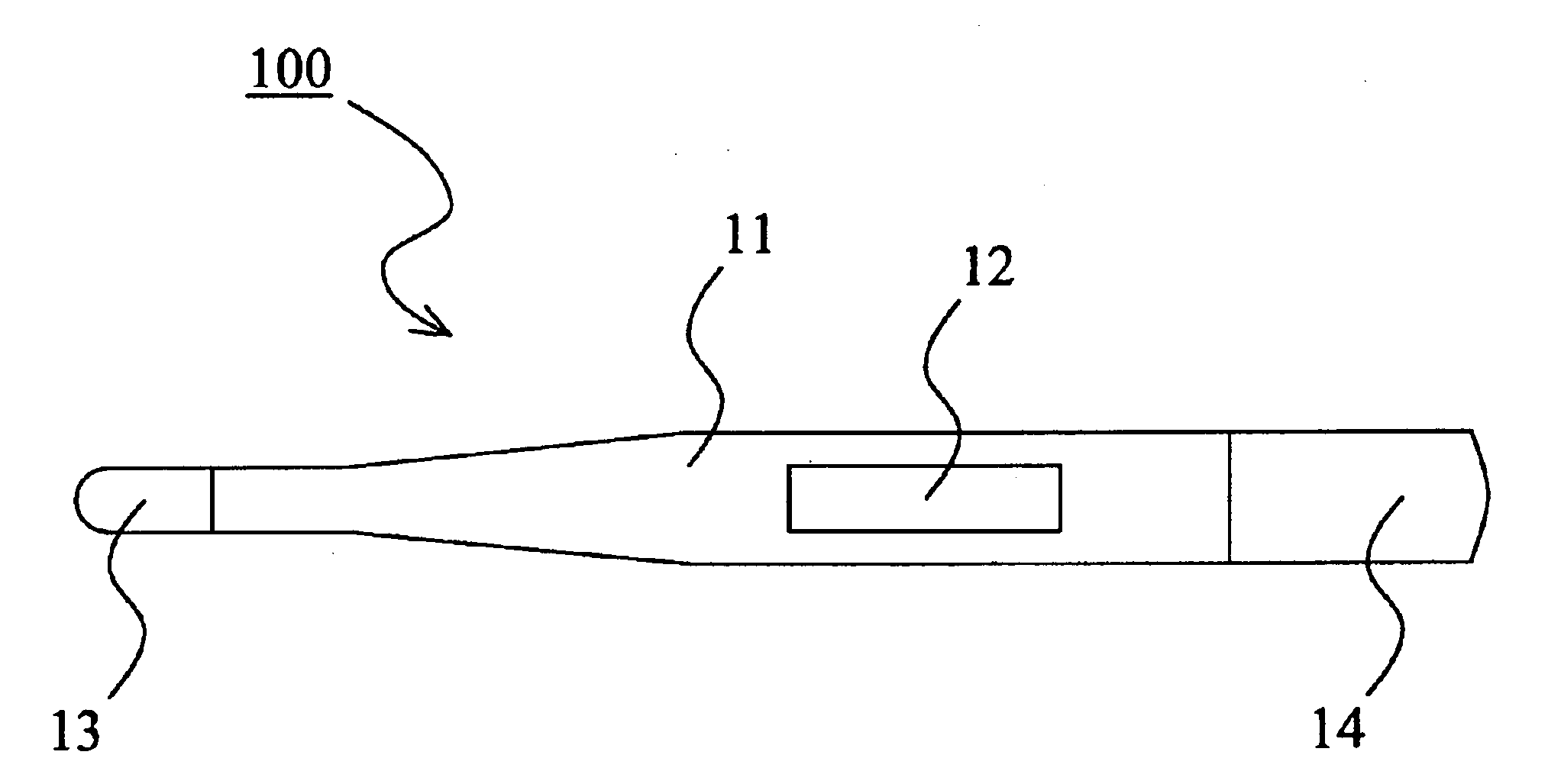
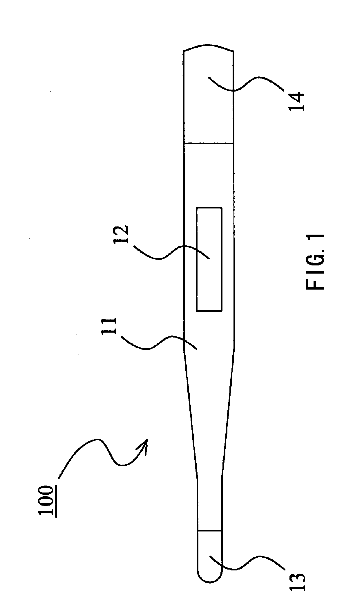
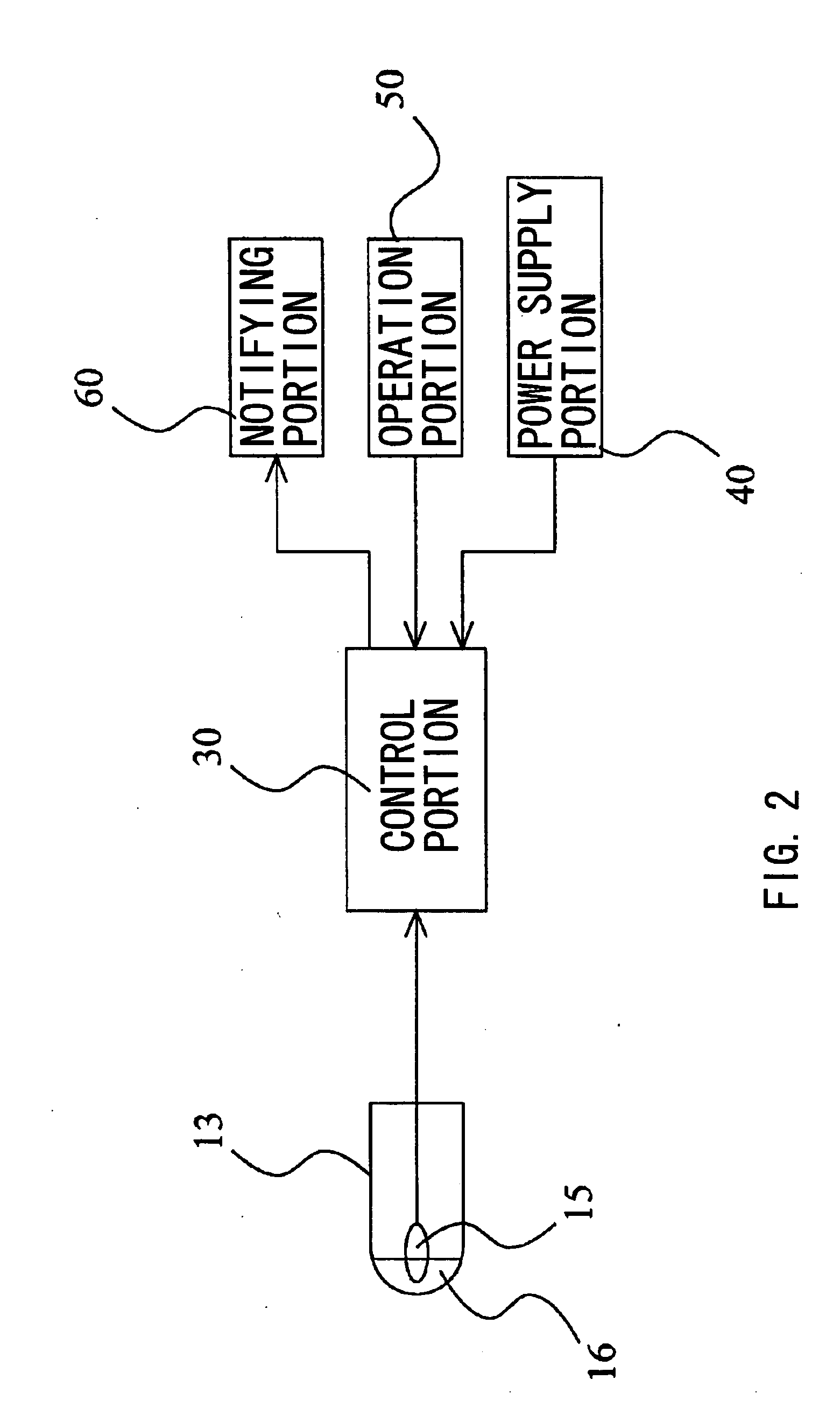
[0046]The electronic thermometer according to the first embodiment of the present invention will be described with reference to FIGS. 1 to 9. FIG. 1 is a plan view of an electronic thermometer according to the first embodiment of the present invention. FIG. 2 is a block diagram of the electronic thermometer according to the first embodiment of the present invention. FIG. 3 is a partially broken perspective view of the electronic thermometer according to the first embodiment of the present invention. FIG. 4 is a perspective view showing a condition in which respective components are incorporated in an inner case according to the first embodiment of the present invention. FIG. 5 is a perspective view showing a condition in which a buzzer and a buzzer cover (pressing member) are incorporated into the inner case according to the first embodiment of the present invention. FIG. 6 is a 6-view diagram of the buzzer cover according to the first embodiment of the present inven...

Example

Second Embodiment

[0066]FIG. 10 shows the second embodiment of the present invention. This embodiment indicates a modification of the buzzer cover as the pressing member. Because the other structure and operation are the same as the first embodiment, like reference numerals are attached to like components and description thereof will not be described. FIG. 10 is a schematic diagram of the buzzer cover according to the second embodiment of the present invention. FIG. 10A is a plan view thereof, FIG. 10B is a sectional view (sectional view taken along the line 10B-10B in FIG. 10A) thereof.

[0067]A buzzer cover 70a of this embodiment is constituted of such material as resin and has plasticity like the first embodiment. This buzzer cover 70a includes a disk-like main body portion 71a, a projecting portion 72a provided in the center of the main body portion 71a, a substantially cylindrical pressing portion 73a provided along the periphery of the main body portion 71a, and a pair of engagin...

Example

Third Embodiment

[0072]FIG. 11 shows the third embodiment of the present invention. The first and second embodiments show an example of structure in which the buzzer cover as a pressing member is provided with the projecting portion and when this projecting portion makes contact with the inner wall face of the outer case, the buzzer cover is flexed. This embodiment shows an example of structure in which the inner wall face of the outer case is provided with the projecting portion and the buzzer cover is flexed by this projecting portion. Because the other structure and operation thereof are the same as the first embodiment, like reference numerals are attached to like components and description thereof will not be described. FIG. 11 shows part of a sectional view in the longitudinal direction of an electronic thermometer according to the third embodiment of the present invention. FIG. 11 shows a section at the same position as FIG. 9 of the first embodiment.

[0073]The buzzer cover 70b...


PUM


Abstract

The electronic thermometer of this invention includes a supporting portion which supports the vicinity of the periphery on one face of a vibration plate, and a buzzer cover having plasticity of pressing the vibration plate against the supporting portion by pressing the vicinity of the periphery of the other face of the vibration plate and further includes a mechanism which presses the vicinity of the center of the buzzer cover on an opposite side to a side provided with the vibration plate in the buzzer cover so as to flex the buzzer cover, thereby pressing the vicinity of the periphery on the other face of the vibration plate with elastic reaction force of the buzzer cover.

Description

[0001]This application claims priority on Japanese Patent Application 2006-139143 filed May 18, 2006.BACKGROUND OF THE INVENTION[0002]1. Field of the Invention[0003]The present invention relates to an electronic thermometer.[0004]2. Description of the Related Art[0005]Conventionally, there has been known an electronic thermometer having a buzzer for notifying user of temperature measurement end time or the like. For such an electronic thermometer, increasing of the sound volume in a small size buzzer is a technical problem.[0006]As art for increasing the sound volume of such a small size buzzer, there have been known arts of forming a resonant space which resonates with vibration sound of a vibration plate provided on the buzzer, and providing a case or the like for supporting the buzzer with a sympathetic vibrating portion which vibrates sympathetically with vibration of the vibration plate (see Japanese Patent Application Laid-Open No. 2004-20241). To exert the resonance action an...

Claims


Application Information

Patent Timeline
IPC IPC(8): G01K3/00G10K9/00G08B17/00G01K13/00
CPCG01K1/02G10K9/22G10K9/12G01K13/002G01K13/20A61B5/01
Inventor NIIYAMA, SHIGETOTOMIOKA, MASAKIMIKI, AKITOSHITERADA, TAKAO
Owner OMRON HEALTHCARE CO LTD
Why Eureka
Try Eureka