Customized surgical guides, methods for manufacturing and uses thereof

a surgical guide and custom technology, applied in the field of surgical guides, can solve the problems of fracture or perforation of the bone, more time-consuming and difficult procedures, and less satisfactory results, and achieve the effect of improving accuracy

Active Publication Date: 2014-05-15
MATERIALISE NV
View PDF4 Cites 19 Cited by
  • Summary
  • Abstract
  • Description
  • Claims
  • Application Information

AI Technical Summary

Benefits of technology

[0037]The customized surgical guides obtainable by the methods according to the present invention not only ensure an improved accuracy compared to prior art guiding tools, but in addition make it possible to provide guidance in complex bone reconstructions. Thus, surgical guides obtainable by the methods of the present invention are novel and inventive over the standard guides or even the alleged “custom” guides disclosed in the prior art.

Problems solved by technology

This procedure is technically more difficult and time-consuming than the primary intervention and the outcome is often less satisfactory, both because there is less bone stock to work with and because the removal of adherent cement or prosthetic components may result in fracture or perforation of the bone.
With each successive joint revision, the risk of infection and symptomatic loosening of the prosthesis may increase substantially.
The treatment of bone and joint defects has gradually become more complex.
Unfortunately, this anchoring process has a number of important drawbacks.
Indeed, deviations in direction and / or location of the screw trajectory often lead to a suboptimal screw traction which may cause soft tissue damage.
As a result, the obtained screw directions are often suboptimal and / or deviate from a preoperative plan.
In addition, a shift of the implant away from the optimal location before pre-drilling has started can cause screw locations, i.e. insertion points of the screw trajectories into the bone, to deviate from a predetermined location.
Unused screw holes badly influence the implant's long-term integrity, unless some other portion of the implant compensates the local decrease in material volume.
This however implies the use of more implant material, for example thickening of the implant, making it more bulky, and / or requires larger contact regions with the bone.
The latter again is detrimental to soft tissue preservation.
Unfortunately, this technology is expensive and intra-operatively very time-consuming.
The use of this device is in practice however limited to anatomical areas which can be extensively exposed or can be easily approached from different directions.
For example, the device does not allow pre-drilling from the ipsilateral side of a bone plate, a procedure which is however often needed, for example in implant surgery of the hemi-pelvis, scapula, or mandible.
These devices can however only be applied in cases of bone repair (following traumata, with multiple bone fragments), and not for bone and joint repair such as in arthroplasty.
Due to reasons of manufacturability, machine set-up time and costs, this guiding solution is limited to large series of off-the-shelf implants, for which it is economically profitable to set up expensive threading machinery.
However, a custom bone guide is not always a guarantee for adequate implant fixation, especially in the case of a patient-specific implant.
This is however unpractical and ineffective since the guide-frame construction has to be taken out, and the implant reinserted while keeping track of the pre-drill locations.
Furthermore, the use of a Kirschner wire to keep track of the pre-drill locations while sliding off the guide and sliding the implant on is not convenient and not fully constrained.

Method used


Image

  • Customized surgical guides, methods for manufacturing and uses thereof
  • Customized surgical guides, methods for manufacturing and uses thereof
  • Customized surgical guides, methods for manufacturing and uses thereof

Examples


examples

[0194]The invention is further illustrated herein below by means of the following non-limiting embodiments.

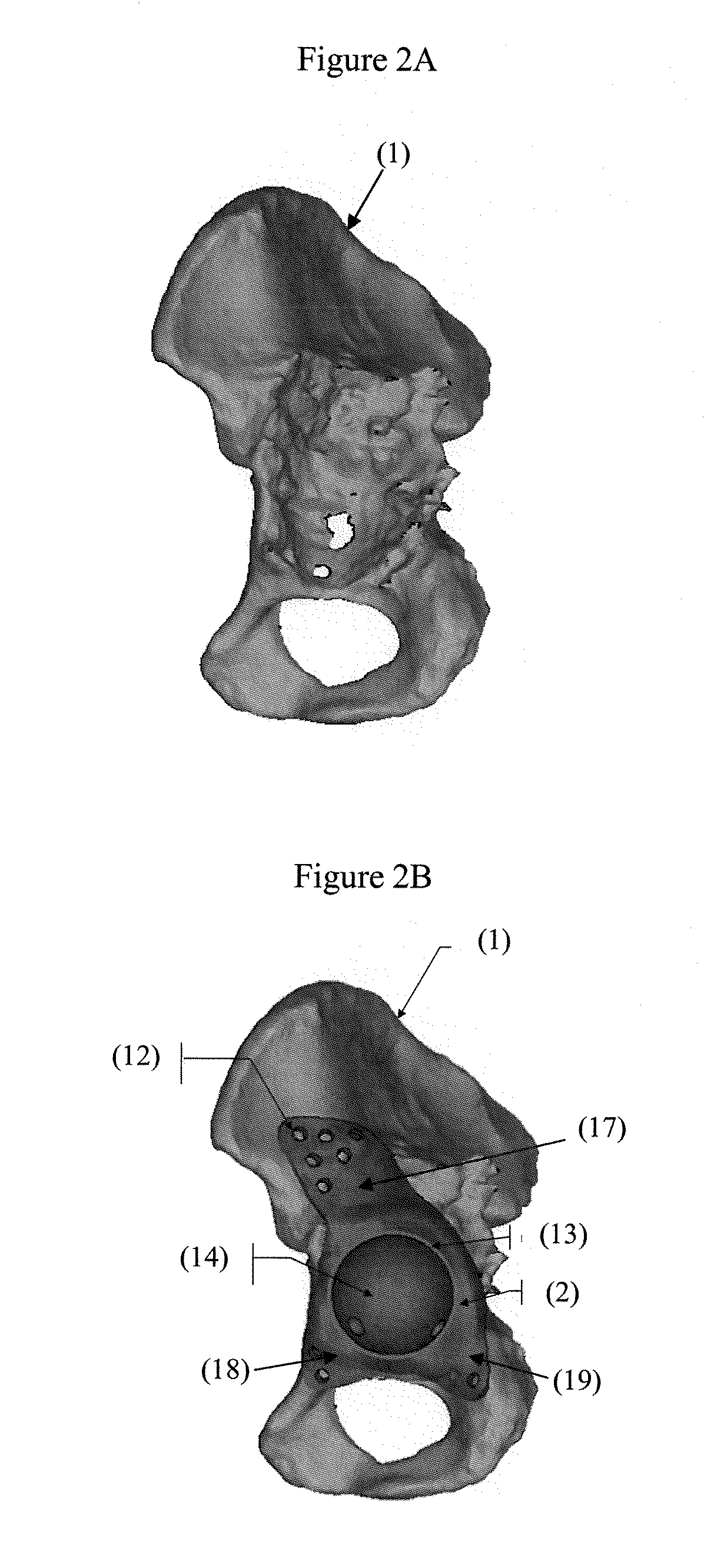
[0195]In particular embodiments, the invention is applied for acetabular cup replacement and the custom surgical guides according to the present invention are designed to fit on a patient-specific acetabular implant.

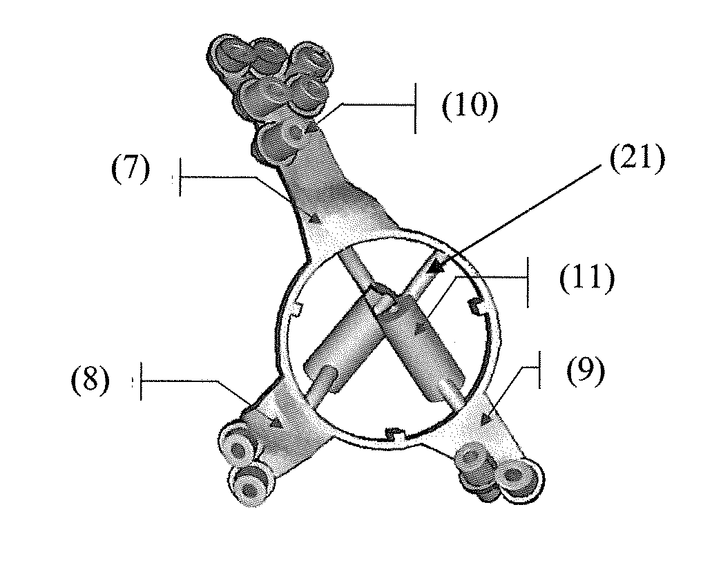
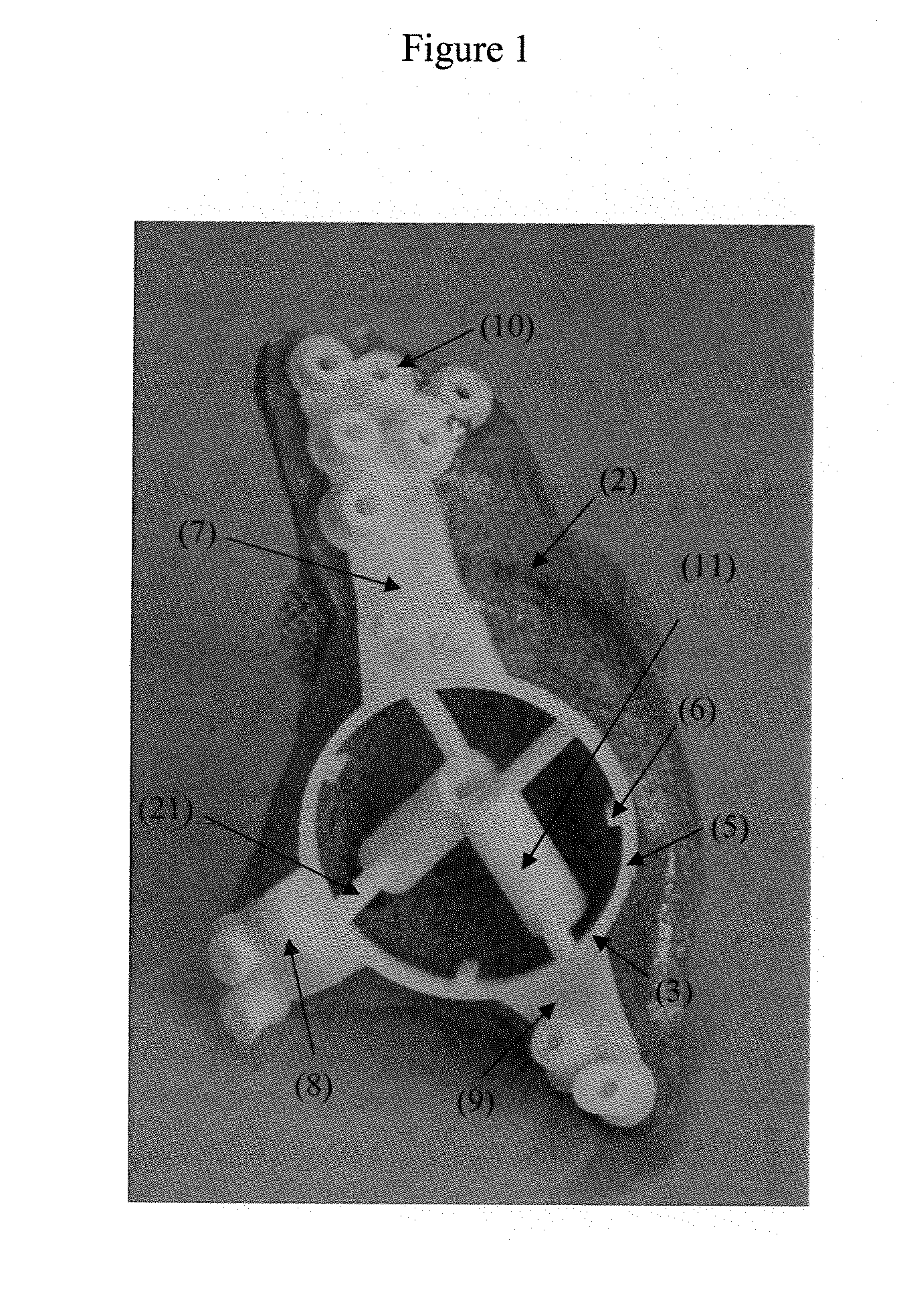
[0196]According to particular embodiments, the connecting structure may be a ring structure and one or more surface structures are designed to fit onto one or more surfaces of the patient-specific acetabular implant. For instance, in these embodiments, the one or more surfaces of the patient-specific acetabular implant may be designed based on specific anatomic features of one or more of the ilium, ischium and / or pubis of the hip joint.

[0197]In particular embodiments, the present invention provides customized surgical guides for a patient-specific acetabular implant comprising one or more surface structures, and one or more guiding elements, wherein at least one of ...


PUM

PropertyMeasurementUnit
trajectory lengthaaaaaaaaaa
morphologyaaaaaaaaaa
surface structureaaaaaaaaaa

Abstract

The invention relates to surgical guides which are of use during reconstructive bone surgery for guiding a surgical instrument or tool. More particularly, the guides are characterized in that they are fitted to the implant rather than to the bone.

Description

CROSS-REFERENCE TO RELATED APPLICATIONS[0001]This application is a continuation-in-part of U.S. application Ser. No. 13 / 515,141, filed Jun. 11, 2012, which is a U.S. national phase of PCT Application No. PCT / EP2010 / 070777, filed Dec. 28, 2010, which claims priority to U.S. Provisional Application No. 61 / 290,673, filed Dec. 29, 2009 and Great Britain Application No. 0922640.8, filed Dec. 29, 2009, the contents of which are hereby incorporated by reference.FIELD OF THE INVENTION[0002]The present invention relates to surgical guides which are of use during reconstructive bone surgery, more specifically during reconstructive joint surgery, for guiding a surgical instrument or tool. The present invention further relates to methods for manufacturing these surgical guides and specific methods for using the surgical guides of the invention in reconstructive bone and joint surgery.BACKGROUND[0003]In most bone or joint arthroplasty, replacement and / or reconstruction surgery procedures, a bone...

Claims


Application Information

Patent Timeline
Patent Type & Authority Applications(United States)
IPC IPC(8): A61B17/17A61F2/34
CPCA61F2/34A61B17/1746A61B17/15A61B17/1666A61B17/17A61B34/10A61B2017/568A61B2034/108A61F2002/30578Y10T29/49826
Inventor GOLDSTEIN, SIMONDEPUYDT, MAARTENGELAUDE, FREDERIK
Owner MATERIALISE NV
Why Eureka
Try Eureka