
A monitoring instrument for diffraction grating light signal with dual channel structure

A diffraction grating, optical signal technology, applied in the coupling of optical waveguides, electromagnetic wave transmission systems, electrical components, etc., can solve the problems of difficult motor control, unfavorable integration or portability, long measurement response time, etc., to achieve easy and precise control. , to achieve the effect of measurement and analysis, and reduce the difficulty of optical adjustment

Active Publication Date: 2007-08-01
SHANGHAI INST OF MICROSYSTEM & INFORMATION TECH CHINESE ACAD OF SCI
View PDF0 Cites 21 Cited by
  • Summary
  • Abstract
  • Description
  • Claims
  • Application Information

AI Technical Summary

Problems solved by technology

This kind of multi-pass monochromator inherits the advantages of compact structure and simplicity of single-pass monochromator and high-resolution of double monochromator, but the response time is very long and the driving structure is complicated, because neither the optical roof reflector nor the grating The size is relatively large, the difficulty of motor control is relatively long and the measurement response time is relatively long, and the size of the network device is still very large, which is not conducive to integration or portability

Method used


Image

  • A monitoring instrument for diffraction grating light signal with dual channel structure
  • A monitoring instrument for diffraction grating light signal with dual channel structure

Examples


Embodiment Construction

[0035] The specific implementation will be described in detail below by way of examples in conjunction with the accompanying drawings.

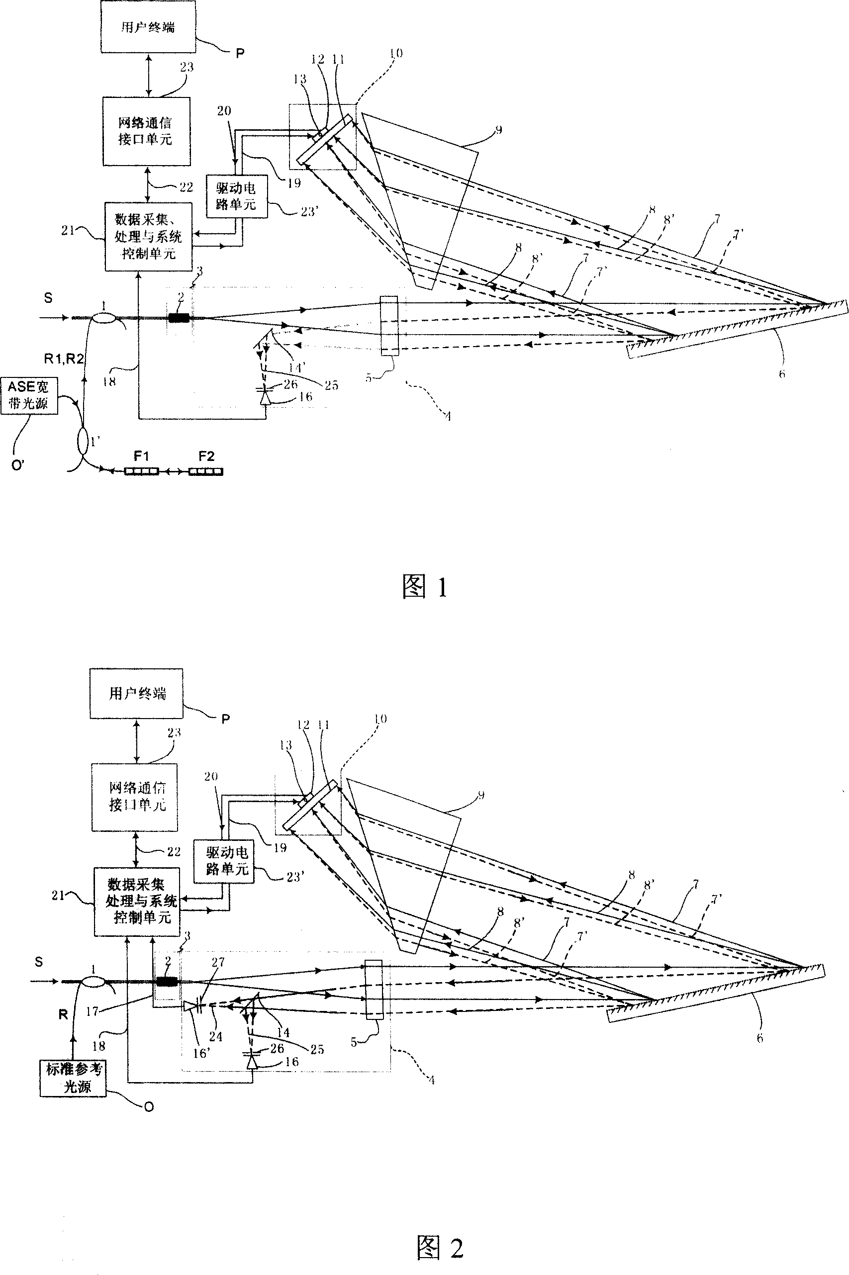
[0036] Figure 1 shows a schematic diagram of the structure of the optical signal monitor, which is based on the Littman structure, combined with a rectangular prism and an optical scanning mirror, making the structure of the instrument more compact. The specific arrangement is: the optical signal S to be measured with a certain bandwidth and the reference optical system composed of the SAE broadband light source O', the fiber Bragg reflection grating F1, F2 with known accurate reflection wavelength and the fiber coupler 1' stably output two Known central wavelength λ r.1 ,λ r.2 Is the incident optical signal, that is, the standard reference wavelengths R1, R2 outside the bandwidth of the DWDM optical signal S to be measured and the DWDM optical signal S to be measured are connected to a polarization control component 3 through a fiber couple...


PUM


Abstract

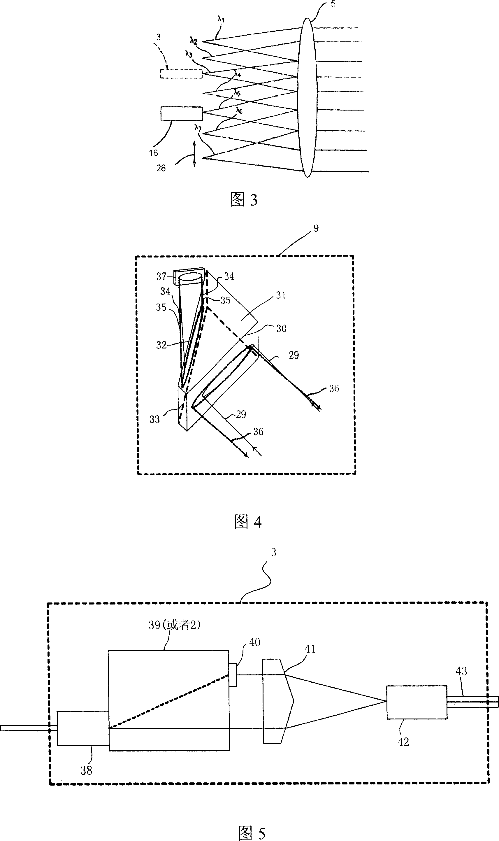
The invention relates to a diffraction grating light signal monitoring instrument with dual channel structure, the monitoring instrument can realize the measuring, monitoring and analyzing of light network communication signal and fiber sensor signal performance, and the miniaturization and intelligentize of high performance light signal monitoring device can be realized. It characterized in that: 1) light scanning lens is set between the diffraction beam of light emitted from the diffraction grating firstly and the second diffraction grating, the wavelength tune function and light signal wavelength dispersion function can be separately accomplished by the light scanning lens and fixed diffraction grating, and the dispersion and filter are accomplished by the same diffraction grating; 2) a right-angle triple prism is set between the light scanning lens and diffraction grating to make the light signal realize the condensation and expanding in space width, 3) standard reference wavelength unit is set before the photoelectric conversion unit; 4) network communication interface unit is set, user can measure, monitor and analyze the light signal property via remote terminal.

Description

technical field [0001] The invention relates to a dual-pass structure diffraction grating optical signal monitor, which belongs to the field of optical communication, optical fiber sensing and optical signal analysis technology, and intelligent measuring instruments. Background technique [0002] In order to improve the dynamic operation level of the communication network and realize the intelligentization of network management, a large number of intelligent communication devices are used in the new generation of optical communication networks, such as intelligent optical amplifiers, dynamic gain equalizers, optical cross-connectors, optical add / drop Multiplexers, tunable dispersion compensators, tunable lasers, tunable filters, etc. Faced with this situation, in order to ensure the long-term healthy operation of the optical network, it is necessary to set up corresponding monitoring instruments in the network nodes to monitor the optical spectrum characteristics, power char...

Claims


Application Information

Patent Timeline
IPC IPC(8): H04B10/08G02B6/27G02B6/26H04B10/079
Inventor 穆参军吴亚明张飞岭张宁
Owner SHANGHAI INST OF MICROSYSTEM & INFORMATION TECH CHINESE ACAD OF SCI
Learn More