Electrical connector with accurately secured contacts

a technology of electrical connectors and contacts, applied in the direction of coupling contact members, fixed connections, coupling device connections, etc., can solve the problems of difficult and problematic insertion of conventional contacts into passageways, inaccurate installation of contacts in corresponding passageways, and inability to accurately insert conventional contacts

Inactive Publication Date: 2005-06-21
HON HAI PRECISION IND CO LTD
View PDF12 Cites 22 Cited by
  • Summary
  • Abstract
  • Description
  • Claims
  • Application Information

AI Technical Summary

Benefits of technology

[0007]An object of the present invention is to provide an electrical connector having precisely positioned contacts for ensuring reliable electrical connection between soldering portions of the contacts and a printed circuit board (PCB).
[0008]To achieve the above object, a connector of the present invention is for electrically connecting pins of a central processing unit (CPU) with a PCB. The connector comprises an insulative housing, a multiplicity of passages defined in the housing, and a multiplicity of conductive contacts secured in corresponding passages. Each passage comprises a receiving portion and a fastening recess. The fastening recess comprises a flared upper portion. Each contact comprises a soldering portion for being soldered to the PCB, a pair of contact portions for engaging with a corresponding output pin of the CPU, and a body portion interconnecting the soldering portion and the contact portions. Two pairs of engaging portions are formed on opposite lateral edges of the body portion respectively. Each engaging portion comprises an upper fixing part and a lower guiding part. Each guiding part is tapered such that a bottom end thereof is narrower and thinner than a top end thereof. When the contact is engaged in the corresponding passage of the housing, the tapered guiding parts and the flared upper portion cooperate to facilitate correct insertion of the contact. That is, even if the contact is initially inserted imprecisely or at an incorrect angle, the guide portions and the flared upper portion can gradually lead the contact to a correct final position and orientation in the passage. Thus the contacts can be precisely fixed in the passages of the housing. This ensures reliable connection between the soldering portions and the PCB, and between the contact portions and the output pins of the CPU.

Problems solved by technology

Conventional contacts are too small to be accurately inserted into the passageways of a housing of a BGA socket.
In addition, the contacts may be inaccurately installed in the corresponding passageways during assembly of the BGA connector.
However, insertion of the contact into the passageway is difficult and problematic.
Forced insertion can result in plastic deformation of the housing at the passageway, and damage to the contact itself.
Retaining the contacts in correct positions while still ensuring coplanarity of the soldering portions of the contacts has not yet been satisfactorily achieved.
There remains unduly high risk of unstable connection between the contacts and the PCB.

Method used


Image

  • Electrical connector with accurately secured contacts
  • Electrical connector with accurately secured contacts
  • Electrical connector with accurately secured contacts

Examples


Embodiment Construction

[0017]Reference will now be made to the drawings to describe the present invention in detail.

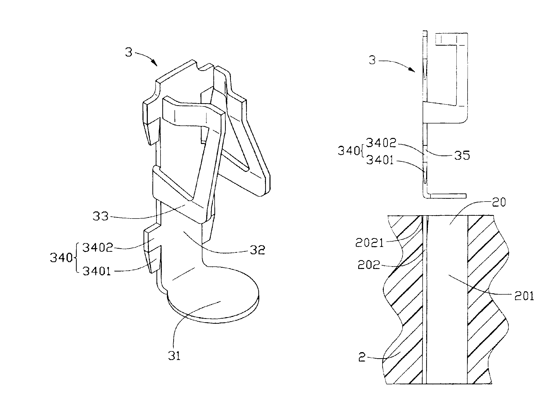
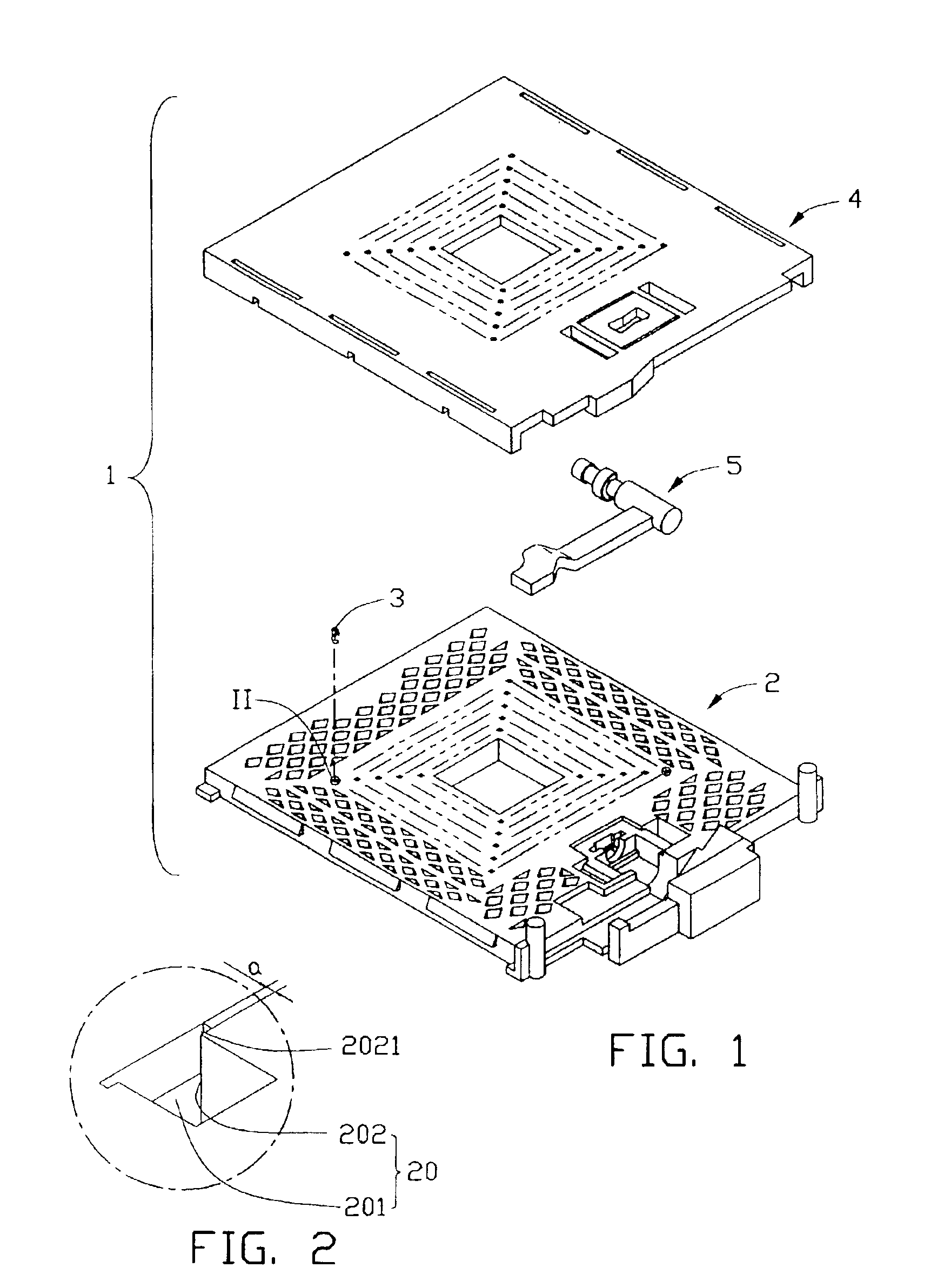
[0018]Referring to FIGS. 1, 2 and 3, an electrical connector 1 in accordance with a preferred embodiment of the present invention is for electrically connecting a central processing unit (CPU) to a printed circuit board (PCB). The connector 1 comprises an insulative housing 2, a multiplicity of conductive contacts 3 secured in the housing 2, a cover 4 slidably mounted on the housing 2, and an actuation device 5 for actuating the cover 4 to slide along the housing 2. The housing 2 defines a multiplicity of passages 20 respectively receiving the contacts 3. Each passage 20 comprises a receiving portion 201 and a fastening recess 202. Each fastening recess 202 comprises a flared upper portion 2021. That is, the fastening recess 202 is largest at a top surface of the housing 2, for facilitating insertion of a corresponding contact 3 into the passage 20.

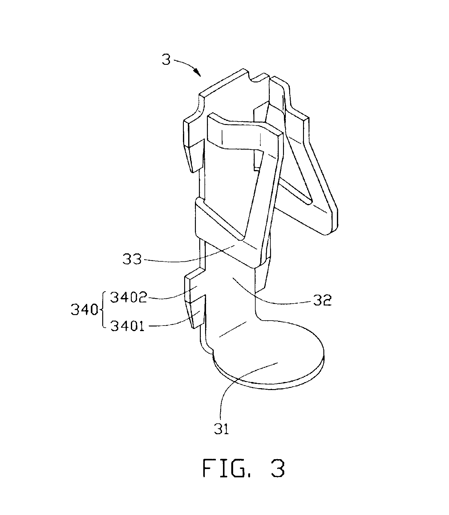
[0019]Each contact 3 comprises a soldering ...


PUM


Abstract

A connector (1) for electrically connecting a central processing unit (CPU) with a printed circuit board (PCB) includes an insulative housing (2), passages (20) defined in the housing, and conductive contacts (3) secured in corresponding passages. Each passage includes a fastening recess (202), and the fastening recess includes a flared upper portion (2021). Each contact includes a soldering portion (31) for being soldered to the PCB, a pair of contact portions (33) for engaging with the CPU, and a body portion (32) interconnecting the soldering portion and the contact portions. Two pairs of engaging portions (340) are formed on opposite lateral edges of the body portion respectively. Each engaging portion includes an upper fixing part (3402) and a lower tapered guiding part (3401). When the contact is engaged in the corresponding passage, the tapered guiding parts and the flared upper portion cooperate to facilitate correct insertion of the contact.

Description

BACKGROUND OF THE INVENTION[0001]1. Field of the Invention[0002]The present invention relates to an electrical connector for electrically connecting an electronic package such as a pin grid array (PGA) chip with a circuit substrate such as a printed circuit board (PCB), and more particularly to an electrical connector providing accurate positioning of conductive contacts therein.[0003]2. Description of the Related Art[0004]Conventional central processing unit (CPU) sockets have contacts received in passageways of an insulative housing, for electrically connecting CPUs to PCBs. The contacts have engaging portions extending from one or two side edges thereof. The thickness of one whole engaging portion is approximately equal to the width of a fastening recess of each passageway. Thus the engaging portions are firmly held in the passageway, and the contact is securely fixed in the housing.[0005]The trend toward miniaturization of electrical connectors and the development of surface mou...

Claims


Application Information

Patent Timeline
Patent Type & Authority Patents(United States)
IPC IPC(8): H01R13/02H01R13/193H01R13/629H01R24/00H01R33/76H01R107/00
CPCH01R13/629H01R13/193H01R12/57
Inventor LEI, JINFENGLI, REN-CHIH
Owner HON HAI PRECISION IND CO LTD
Why Eureka
Try Eureka