Stabilizer for video camera

a technology for stabilizing devices and video cameras, applied in the direction of camera body details, instruments, stands/trestles, etc., can solve the problems of not being able to adjust and adjust the stabilizer, and achieve the effect of accurately fixing a video camera and simple structur

Active Publication Date: 2018-12-18
WEI CHENGYUN
View PDF6 Cites 21 Cited by
  • Summary
  • Abstract
  • Description
  • Claims
  • Application Information

AI Technical Summary

Benefits of technology

[0030]The stabilizer of the present invention possesses the following benefits as compared to other existing technologies: the stabilizer of the present invention is able to adjust the relative position of its three axes and the mounting position of a video camera, which enables the stabilizer of the present invention to match with various video cameras. The stabilizer of the present invention is simply structured and can accurately fix a video camera.

Problems solved by technology

The shortcomings of above-mentioned technology are that three axes of these stabilizers are not adjustable, the stabilizing spot of these stabilizers for stabilizing video cameras (ie., mounting position or mounting spot of the video camera) is not adjustable either.

Method used


Image

  • Stabilizer for video camera
  • Stabilizer for video camera
  • Stabilizer for video camera

Examples


embodiment 1

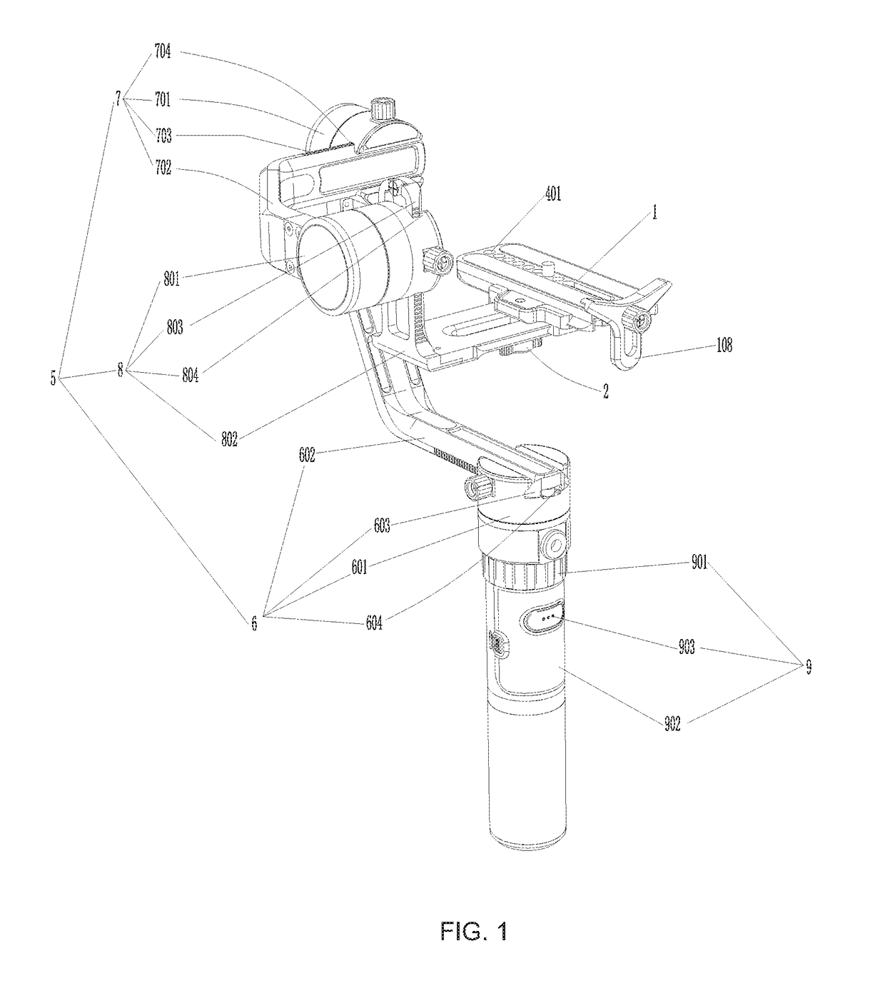
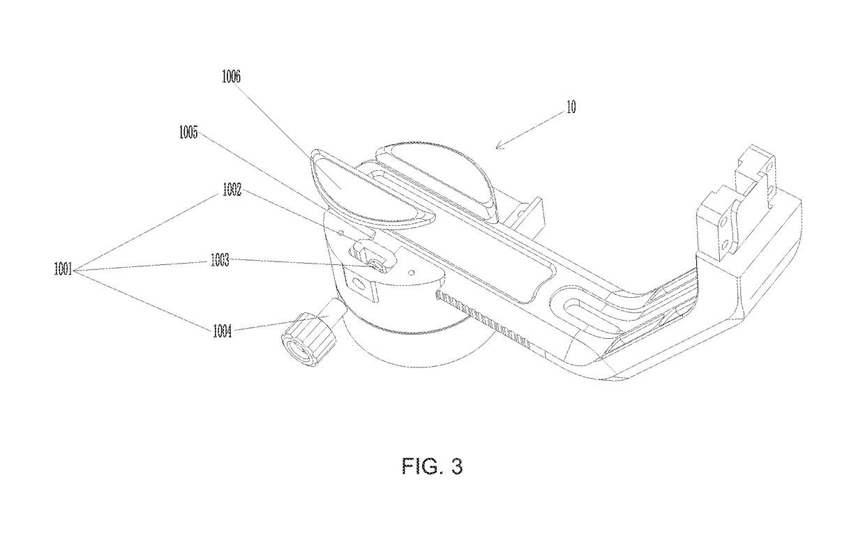
[0034]Embodiment 1 provides a stabilizer for video camera, as shown in FIGS. 1-3, which comprises a mounting stage 1, a first retaining assembly 2, a second retaining assembly 3, a fixing assembly 4, a 3-dimensional adjusting device 5, a first transverse movement assembly 6, a second transverse movement assembly 7, a vertical movement assembly 8, a handgrip 9 and a damping assembly 10.

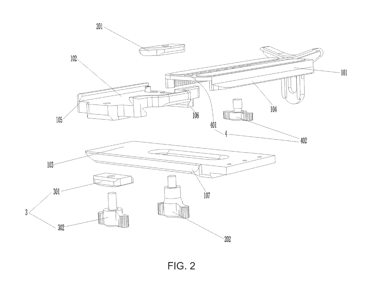
[0035]Referring to FIGS. 1-2, the mounting stage 1 is configured for holding a video camera and comprises a first slider 101, a second slider 102, a third slider 103, the first retaining assembly 2, the second retaining assembly 3 and the fixing assembly 4. The second slider 102 is situated beneath the first slider 101, the third slider 103 is situated beneath the second slider 102. The first slider 101 makes forward and backward movement relative to the second slider 102, the second slider 102 makes left and right movement relative to the third slider 103.

[0036]Two first slide rails 104 are provided a...

embodiment 2

[0046]The distinction between embodiment 2 and embodiment 1 is that the handgrip in embodiment 2 is held in both hands and could be switched to single hand-held grip by loosening the locking ring 901.


PUM


Abstract

The present invention provides a stabilizer for video camera, the stabilizer has a mounting stage holding a video camera and a three-dimensional adjusting device. The three-dimensional adjusting device comprises a first transverse movement assembly, a second transverse movement assembly and a vertical movement assembly, the first transverse movement assembly comprises a first motor and a first connecting arm piece, the second transverse movement assembly comprises a second motor and a second connecting arm piece, the vertical movement assembly comprises a third motor and a third connecting arm piece, the mounting stage being connected to the third connecting arm piece. Each of said connecting arm pieces is provided with a guide rail, and each of said motors is provided with a guide slot that matches with the corresponding guide rail.

Description

CROSS-REFERENCE TO PRIOR APPLICATION[0001]This application claims the benefit of Chinese Patent Application No. 201710450897.1 filed on Jun. 15, 2017, the contents of which are incorporated herein by reference.TECHNICAL FIELD[0002]The present invention relates to a stabilizer for a video camera.BACKGROUND OF THE INVENTION[0003]Stabilizers for video camera is used for a supporting worktable that is for setting up video camera and video camera is held by the stabilizer. Video camera lens could be adjusted through adjusting the stabilizer so as to obtain a proper shooting for certain objects.[0004]Current technology has disclosed several video camera stabilizers. CN patent application No. 201110295102.7 disclosed a stabilizer for a video camera. An upper arm of the stabilizer consists of one stabilizing spring and two square light-weighted aluminum alloy plates, and a lower arm of the stabilizer consists of two springs and three square light-weighted aluminum alloy plates. The upper en...

Claims


Application Information

Patent Timeline
Patent Type & Authority Patents(United States)
IPC IPC(8): F16M11/04G03B17/56
CPCG03B17/561F16M11/045F16M11/046F16M11/048F16M11/043F16M11/16G03B17/563F16M11/18F16M11/2092F16M11/24F16M13/04F16M2200/041
Inventor WEI, CHENGYUN
Owner WEI CHENGYUN
Why Eureka
Try Eureka