Incapacity monitor

a monitor and inability technology, applied in the field of inability monitors, can solve problems such as affecting the ability of operators

Inactive Publication Date: 2009-02-05
OPTALERT
View PDF18 Cites 12 Cited by
  • Summary
  • Abstract
  • Description
  • Claims
  • Application Information

AI Technical Summary

Benefits of technology

[0017]If the operator does not respond an emergency procedure can be implemented. The emergency procedure will vary according to the type of veh

Problems solved by technology

The detection of drowsiness is of importance because drowsiness impairs the ability of operators of a

Method used


Image

  • Incapacity monitor
  • Incapacity monitor
  • Incapacity monitor

Examples


Embodiment Construction

[0027]The eye monitoring apparatus used in this invention is of the same kind as described in the inventor's earlier patent application WO 03 / 039358. WO 03 / 039358 described glasses with transducers (IR-LEDs and phototransistors) on both eyes. The reason for this was that binocular coordination changed with drowsiness which made it essential to record from both eyes. However, based on further research by the inventor, it appears that the measurement of binocular coordination becomes more inaccurate as drowsiness progresses. Thus where the measurement of binocular coordination is not required recordings from one eye are sufficient for all other parameters.

[0028]It is now preferred to position two infrared emitters and at least one photo transistor detector located on the lower frame member below one eye. During fitting of the device to an individual the emitter which provides the best signal is chosen for that individual.

[0029]Currently, video camera methods for monitoring drowsiness ...


PUM


Abstract

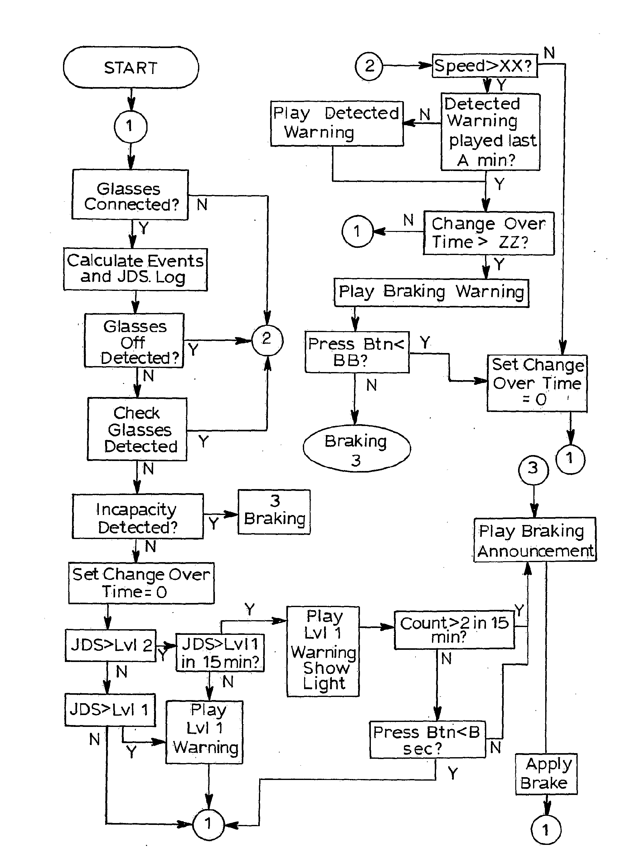
A method of monitoring incapacity of a subject which includes the steps of continuously monitoring eye and eyelid movement of at least one eye of the subject; analyzing eye and eyelid movements to obtain measures of ocular quiescence and the duration of an interval of no eye or eyelid movement; and if the duration of ocular quiescence exceeds a predetermined value providing a potential incapacity warning and requesting a response within a predetermined period, and applying an emergency procedure if no response is made within a predetermined interval.

Description

[0001]This invention relates to monitoring inattention and particularly incapacity in vehicle drivers or machinery operators.BACKGROUND TO THE INVENTION[0002]The detection of drowsiness is of importance because drowsiness impairs the ability of operators of a wide range of equipment including motor vehicles, aircraft and boats as well as industrial equipment[0003]WO 03 / 039358 disclosed an alertness monitor that used infra red light to measure the amplitude and velocity of eyelid and eye movements to derive a measure of Drowsiness on a scale. This monitor sought to provide a real time alertness monitor that can provide a calibrated measure of the operator's alertness. There is a recent concern with the problem of driver distraction, not just drowsiness. By distraction they mean displacement of the driver's focus of visual attention from the driving task, either to a non-visual task (eg talking to other people in the vehicle, or the use of mobile phones), or to an alternative, visual ...

Claims


Application Information

Patent Timeline
IPC IPC(8): G06K9/00
CPCA61B3/113A61B5/1103A61B5/18A61B5/4809A61B2503/22B60W10/184A61B5/6803A61B5/6821B60K28/066A61B5/163
Inventor JOHNS, MURRAY
Owner OPTALERT
Why Eureka
Try Eureka