Automatic Block Making Machine

Inactive Publication Date: 2009-02-05
HYDRAFORM DEV
View PDF3 Cites 1 Cited by
  • Summary
  • Abstract
  • Description
  • Claims
  • Application Information

AI Technical Summary

Benefits of technology

[0017]The operation of the apparatus is preferably controlled by an automatic or semi-automatic electro/hydraulic control system.
[0018]The apparatus preferably includes a hydraulic operating system having a reservoir for hydraulic fluid, a pump for pressurising the hydraulic fluid, and a plurality of valves arranged to control the operation of respective hydraulic actuators to operate the upper and lower rams and to move the compression chamber between the respective positions thereof in

Problems solved by technology

However, even the more sophisticated machin

Method used


Image

  • Automatic Block Making Machine
  • Automatic Block Making Machine
  • Automatic Block Making Machine

Examples


Embodiment Construction

[0024]Although various manually and hydraulically operated block forming machines are available, for example the machine described in South African patent no. 2002 / 5183, such machines generally still require a number of personnel to operate them, which tends to increase the cost of operating the machines and may lower their productivity. The present invention therefore aims to provide a greater degree of automation in a machine of this general kind.

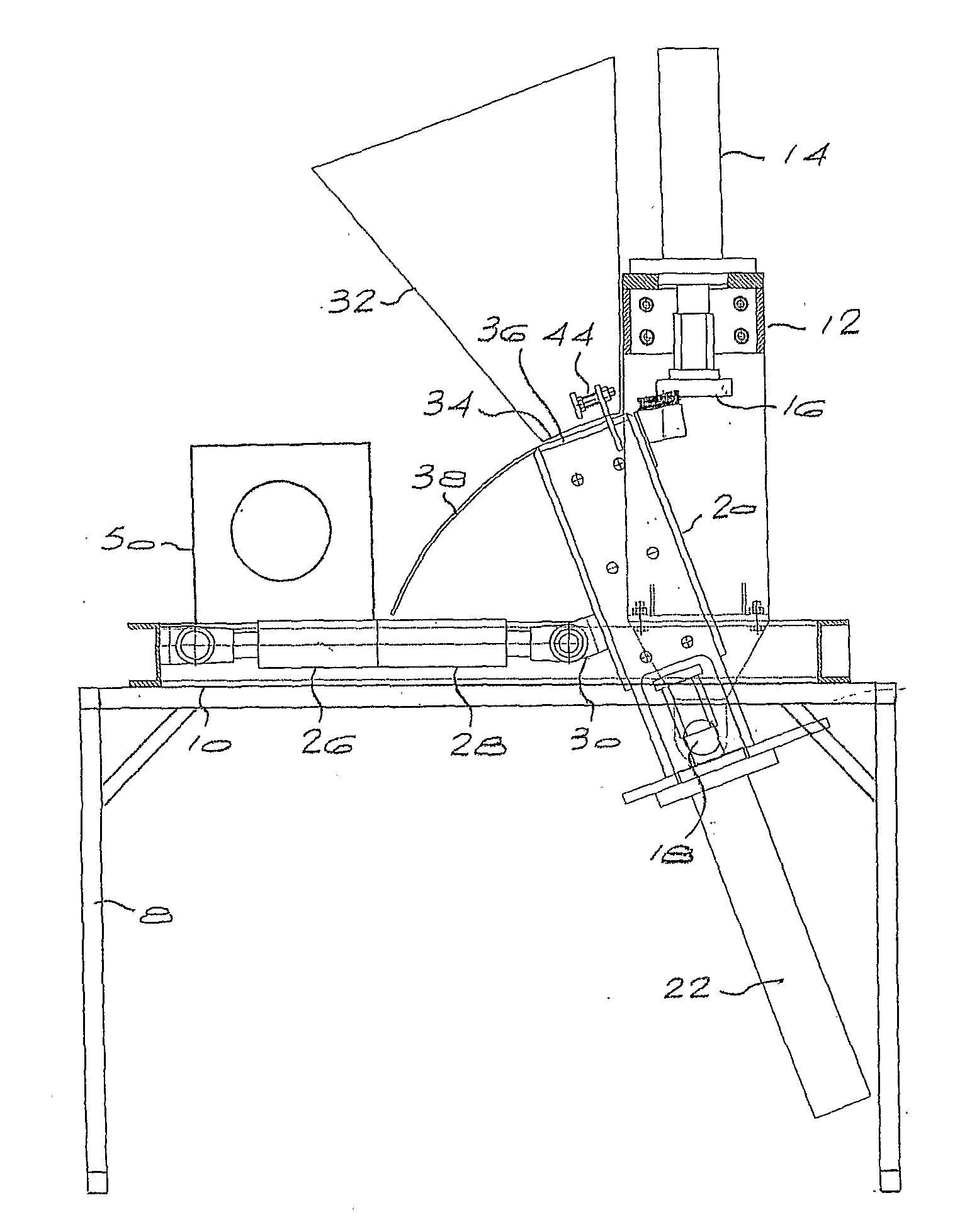
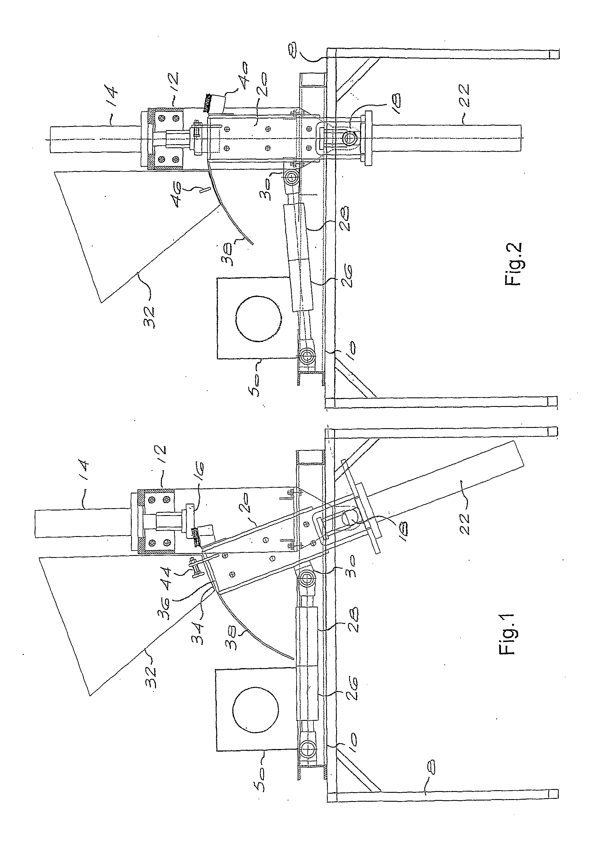
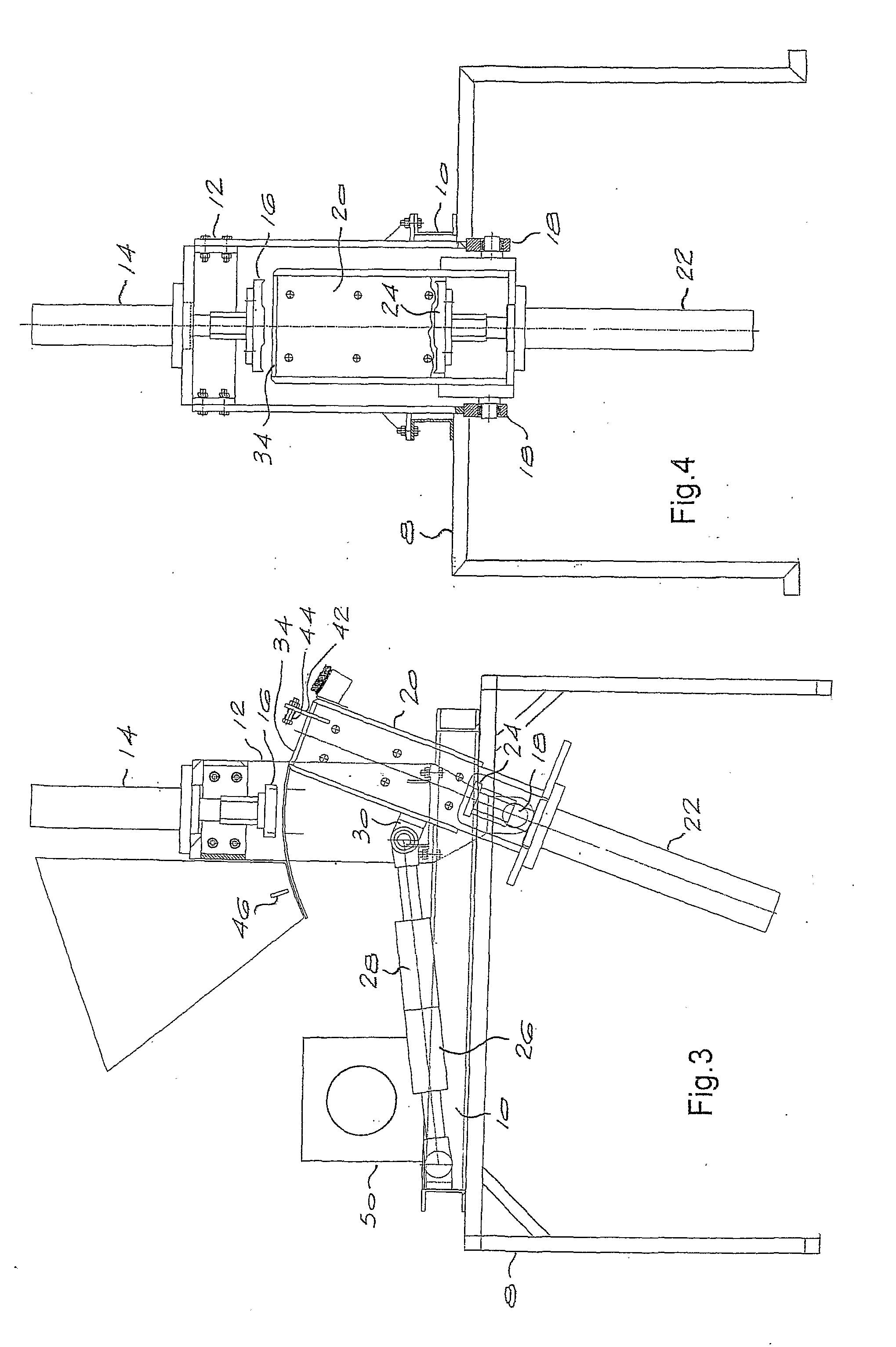
[0025]Referring now to FIGS. 1 through 4, the essential components of an automatic block making machine according to the invention are shown. The machine will typically be mounted in use on a mobile frame 8, as shown, or a trailer, together with an electric or internal combustion motor and associated hydraulic pump, and the necessary control circuits (see below). Other mounting and drive arrangements are of course possible.

[0026]The machine comprises a horizontal mounting frame 10 formed from steel sections wielded together to define a re...


PUM

PropertyMeasurementUnit
Pressureaaaaaaaaaa

Abstract

The invention provides block forming apparatus with a compression chamber having upper and lower opposed ends, and defining a common inlet and outlet at the upper end of the compression chamber, via which the compression chamber can be charged with block forming material, and via which a formed block can be ejected from the compression chamber. The compression chamber is mounted pivotably on a frame so that it can be pivoted sequentially through different positions. A lower ram is movable between an extended position, to compress the block forming material from the bottom, and a retracted position. An upper ram is movable between a retracted position clear of the common inlet and outlet, and a closed position. A set of actuators move the compression chamber between a first, loading position, a second, compacting position and a third, ejection position.

Description

BACKGROUND OF THE INVENTION[0001]This invention relates to an automated apparatus for forming blocks such as building blocks.[0002]A number of block making machines exist, ranging from simple hand-operated machines to more complex hydraulically operated machines. However, even the more sophisticated machines can be quite labour intensive to operate.[0003]It is an object of the invention to provide block making apparatus that offers a degree of automation and is relatively non-labour intensive to operate.SUMMARY OF THE INVENTION[0004]According to the invention there is provided block forming apparatus comprising:[0005]a compression chamber having upper and lower opposed ends;[0006]a common inlet and outlet at the upper end of the compression chamber, via which the compression chamber can be charged with block forming material, and via which a formed block can be ejected from the compression chamber;[0007]a frame arranged to support the compression chamber;[0008]a lower ram movable be...

Claims


Application Information

Patent Timeline
IPC IPC(8): B28B3/02
CPCB28B3/08B30B11/14B30B11/12B28B5/04
Inventor BOOYSEN, QUINTIN
Owner HYDRAFORM DEV
Why Eureka
Try Eureka