Control apparatus for voltage converting apparatus

a voltage conversion apparatus and control apparatus technology, applied in the direction of process and machine control, capacitor propulsion, instruments, etc., can solve the problems of difficult to keep detecting accurate current values all the time, surely not easy to perform appropriate control at appropriate timing at the time of one-arm drive, etc., to achieve the effect of preventing the problem

Active Publication Date: 2014-12-11
DENSO CORP
View PDF2 Cites 6 Cited by
  • Summary
  • Abstract
  • Description
  • Claims
  • Application Information

AI Technical Summary

Benefits of technology

[0037]In this case, since the zero timing at which the average value of the drive current is zero is accurately estimated by the zero timing estimating device, the arm change control by the current controlling device can be preferably performed. It is therefore possible to effectively prevent the problem caused by a shift of arm change timing from the zero timing.

Problems solved by technology

The offset can be corrected, for example, if no current flows; however, the correction is hard if the current flows.
It is thus hard to keep detecting an accurate current value all the time by using the current; sensor.
Therefore, it is surely far from easy to perform appropriate control at appropriate timing at the time of the one-arm drive.
As described above, in the case of the one-arm drive described in the Patent documents 1 to 3 described above, there is such a technical problem that it is likely impossible to perform the appropriate control in changing the arm because it is hard to accurately detect the current value near the zero current.

Method used


Image

  • Control apparatus for voltage converting apparatus
  • Control apparatus for voltage converting apparatus
  • Control apparatus for voltage converting apparatus

Examples


Embodiment Construction

[0049]Hereinafter, an embodiment of the present invention will be explained with reference to the drawings.

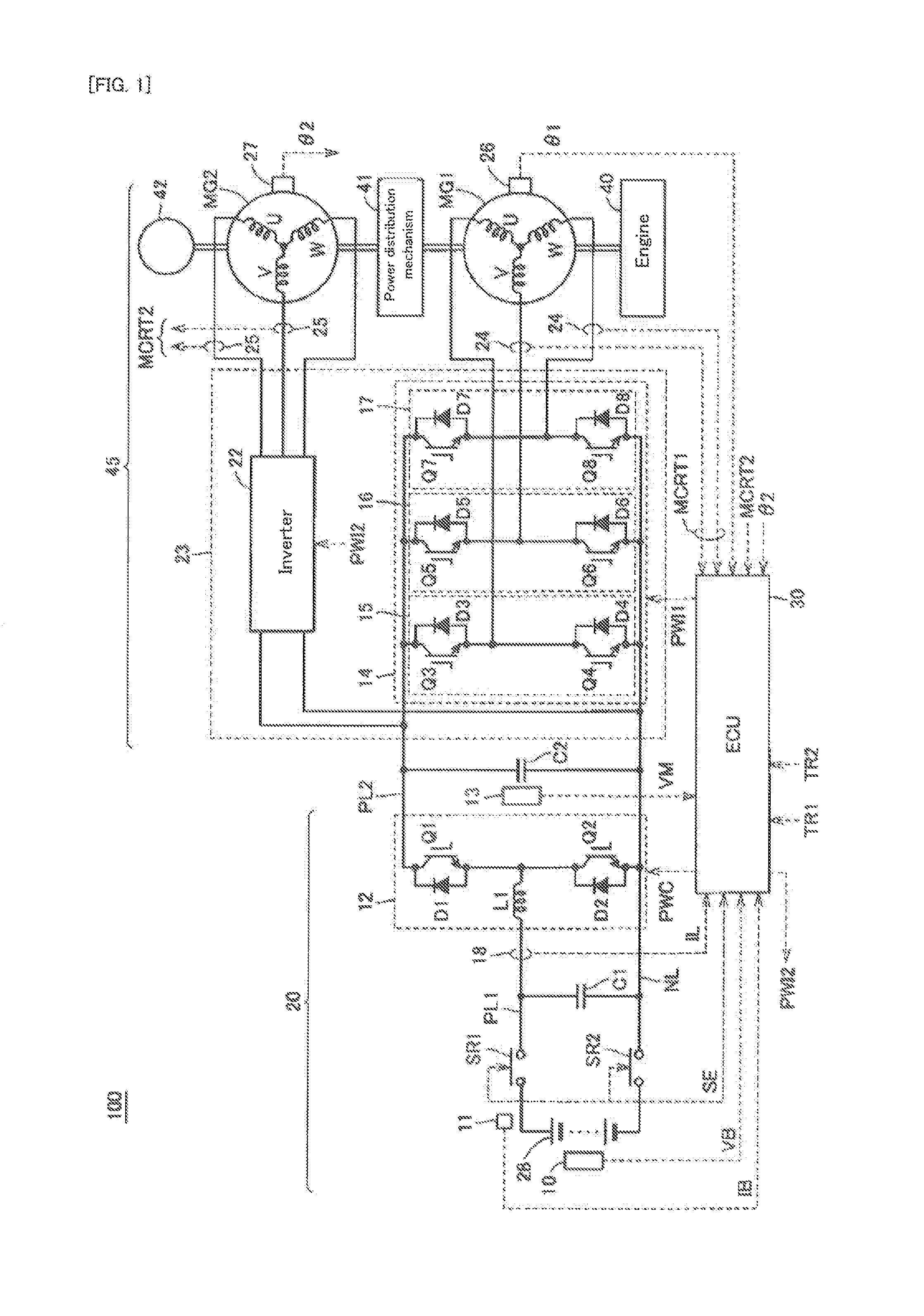
[0050]Firstly, an entire configuration of a vehicle equipped with a control apparatus for a voltage converting apparatus in the embodiment will be explained with reference to FIG. 1. FIG. 1 is a schematic diagram illustrating the entire configuration of the vehicle equipped with the control apparatus for the voltage converting apparatus in the embodiment.

[0051]In FIG. 1, a vehicle 100 equipped with the control apparatus for the voltage converting apparatus in the embodiment is configured as a hybrid vehicle using an engine 40 and motor generators MG1 and MG2 as a power source. The configuration of the vehicle 100, however, is not limited to this example, and can be also applied to a vehicle which can drive due to electric power from an electrical storage device (e.g. an electric vehicle and a fuel-cell vehicle) or the like. Moreover, in the embodiment, an explanation will be gi...


PUM


Abstract

A control apparatus (30) for a voltage converting apparatus controls a voltage converting apparatus (12) configured to realize one-arm drive by alternatively switching on first and second switching elements (Q1, Q2). The control apparatus for the voltage converting apparatus is provided with: a switching control signal generating device configured to generate switching control signals (PWI1, PWI2) for changing on and off the respective first and second switching elements; a current detecting device configured to detect a current value (IL) of a drive current flowing through the first or second switching element, at rise timing of the switching control signal, when the one-arm drive is changed between one-arm drive using the first arm and one-arm driving using the second arm; a current estimating device configured to estimate an average value of the drive current by using the detected current value; and a current controlling device configured to control the drive current on the basis of the estimated average value.

Description

TECHNICAL FIELD [0001]The present invention relates to a control apparatus for a voltage converting apparatus mounted, for example, on a vehicle or the like.BACKGROUND ART[0002]Recently, as an environmentally-friendly vehicle, attention has been drawn to an electrically-driven vehicle which is equipped with an electrical storage device (such as, for example, a secondary battery and a capacitor) and which drives using a driving force generated from electric power stored in the electrical storage device. The electrically-driven vehicle includes, for example, an electric vehicle, a hybrid vehicle, a fuel-cell vehicle, or the like.[0003]The electrically-driven vehicle is provided, in some cases, with a motor generator which generates the driving force for driving in response to the electric power from the electrical storage device upon departure and acceleration, and which generates electricity due to regenerative braking upon braking and stores electrical energy in the electrical stora...

Claims


Application Information

Patent Timeline
Patent Type & Authority Applications(United States)
IPC IPC(8): H02M3/158B60L50/15B60L50/16
CPCH02M3/158B60L7/14B60L15/007B60L15/2009B60L2210/10B60L2210/40B60L2220/14B60L2240/421B60L2240/423B60L2240/529B60L2240/80B60L2260/44B60L50/16B60L50/40B60L50/61H02M3/1588Y02T10/62Y02T10/64Y02T10/70Y02T10/7072Y02T10/72
Inventor SUNAHARA, SHOHEI
Owner DENSO CORP
Why Eureka
Try Eureka