
Induction driven light module and use thereof

a technology of induction-driven light and modules, which is applied in the field of induction-driven light modules, can solve the problems of adding to the cost of the device, adding to the bulk of the handpiece, and the inability to freely choose the wavelength of leds capable of providing the necessary intensity for pd

Inactive Publication Date: 2009-02-05
NATIONAL YANG MING UNIVERSITY
View PDF5 Cites 23 Cited by
  • Summary
  • Abstract
  • Description
  • Claims
  • Application Information

AI Technical Summary

Problems solved by technology

These devices require complicated liquid cooling circuits which would add to the cost of the device and add to the bulk of the hand piece, which is disadvantageous for invasive use.
However, the wavelengths of LED's capable of providing the necessary intensity for PDT cannot freely be chosen within that range.

Method used


Image

  • Induction driven light module and use thereof
  • Induction driven light module and use thereof

Examples


example 1

Preparation of Module of Present Invention

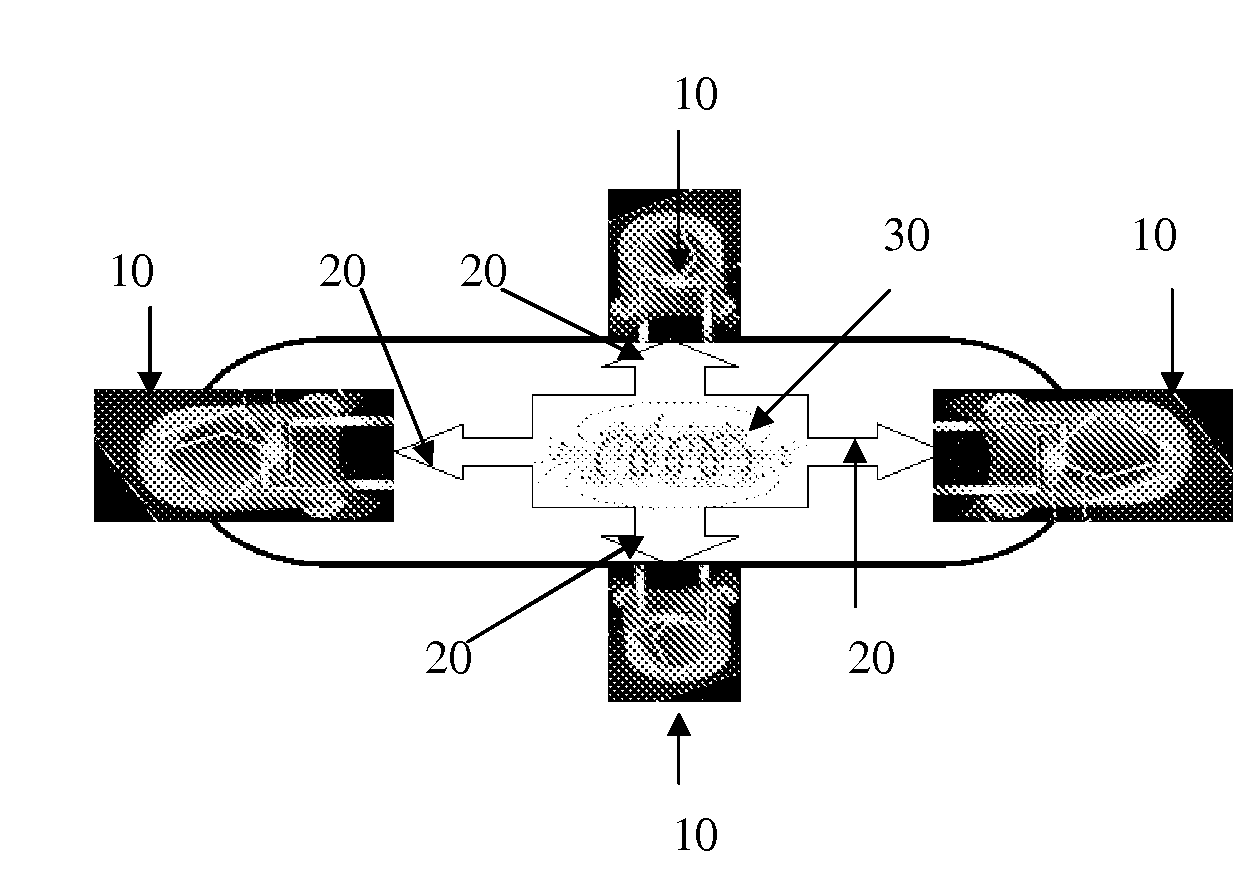
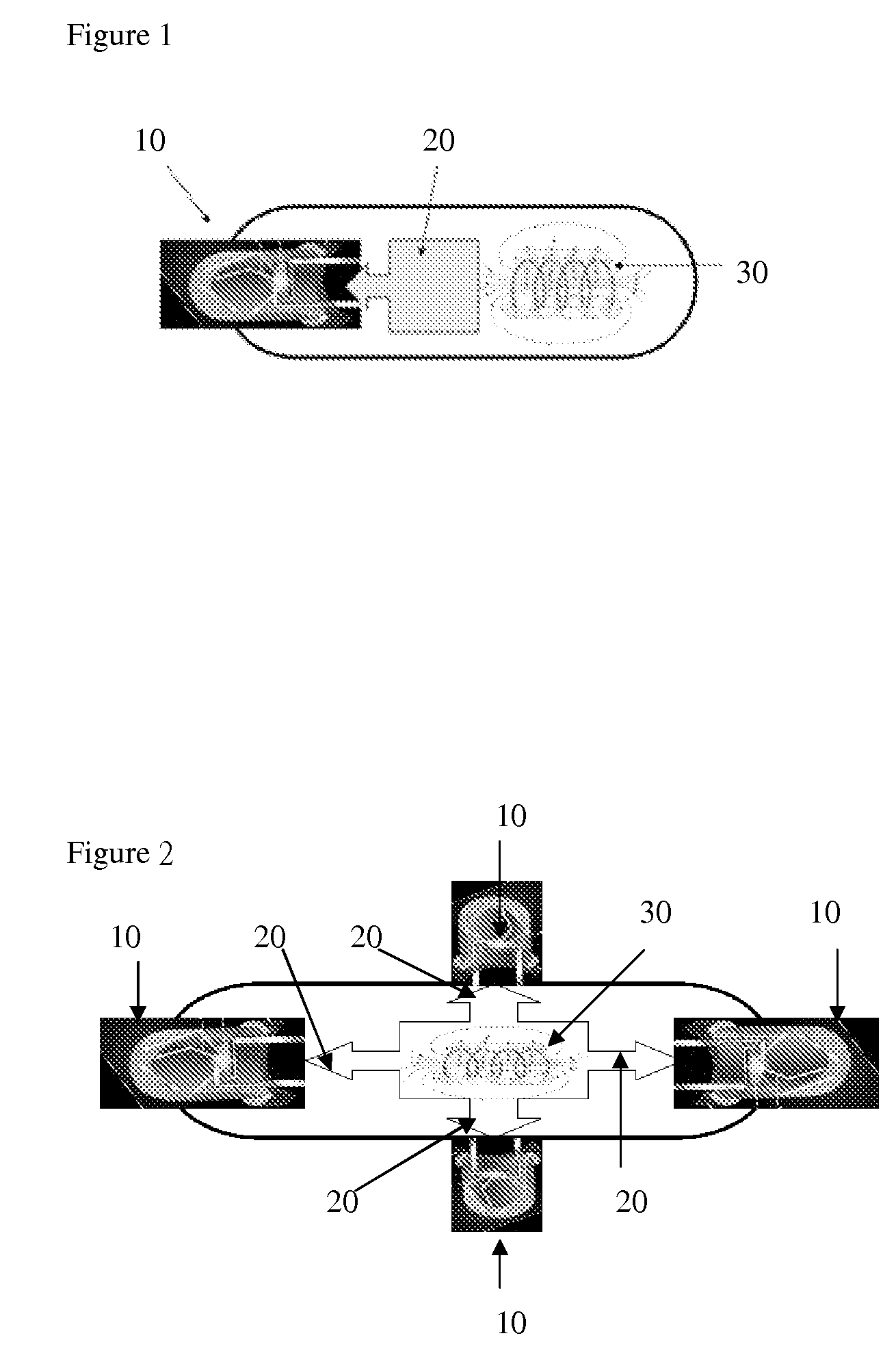
[0045]Referring now to FIG. 1, a light generating device 10 (such as LED) was electrically coupled to a driver 20 having coil module 30 to form the module of the present invention. To avoid contacting the tissue, the use of a water-tight material such as polyurethane or polyester to seal the module of the present invention.

example 2

Application of Present Module to Patient Suffering Cancer

[0046]A patient suffering liver cancer was selected to perform photodynamic therapy. The tissue nearby hepatoma was incised by surgery, was coated with Photofrin® and was placed with the module of the present invention. Then, the wound was closed and LED started to irradiate the hepatoma through inducing the coil based driver by alternating magnetic field.


PUM


Abstract

The present invention relates to an induction driven light module. In particular, the present invention is directed to an induction driven LED or LD module for photodynamic therapy, entertainment or decoration. The present invention also relates to a method for treating cancer, tumor or other ailments.

Description

FIELD OF THE INVENTION[0001]The present invention relates to an induction driven light module. In particular, the present invention is directed to an induction driven LED or LD module for photodynamic therapy, entertainment or decoration use. The present invention also relates to a method for treating cancer, tumor or other ailments.BACKGROUND OF THE INVENTIONPDT[0002]Photodynamic therapy (PDT) has been proposed as one alternative for treating prostatic tissue. U.S. Pat. No. 5,514,669 (Selman), which is herein incorporated by reference in its entirety, describes a method of treating the symptoms associated with BPH or prostatitis comprising sensitizing the prostatic tissue with an effective amount of photosensitive composition which accumulates in the tissue and exposing the sensitized tissue to a light source whereby the photosensitive composition absorbs the light or undergoes a photochemical reaction.[0003]PDT or photodynamic therapy has become a recognized means of treating cert...

Claims


Application Information

Patent Timeline
Patent Type & Authority Applications(United States)
IPC IPC(8): A61B18/18
CPCA61N1/3787A61N5/062A61N2005/0659A61N2005/0652A61N2005/0651
Inventor KAO, FU-JENYANG, CHYUN-YULI, CHENG-CHUN
Owner NATIONAL YANG MING UNIVERSITY
Learn More