Rail arrangement for firearm

a rail arrangement and firearm technology, applied in the field of rail arrangement of firearms, can solve the problems of reducing the shooting accuracy, wasting ammunition, and even losing the life of the user, and achieve the effect of enhancing the practical use of the accessory

a rail arrangement and firearm technology, applied in the field of rail arrangement of firearms, can solve the problems of reducing the shooting accuracy, wasting ammunition, and even losing the life of the user, and achieve the effect of enhancing the practical use of the accessory

US20090038198A1Inactive Publication Date: 2009-02-12YU HERMAN

Image

  • Rail arrangement for firearm
  • Rail arrangement for firearm
  • Rail arrangement for firearm

Examples


Embodiment Construction

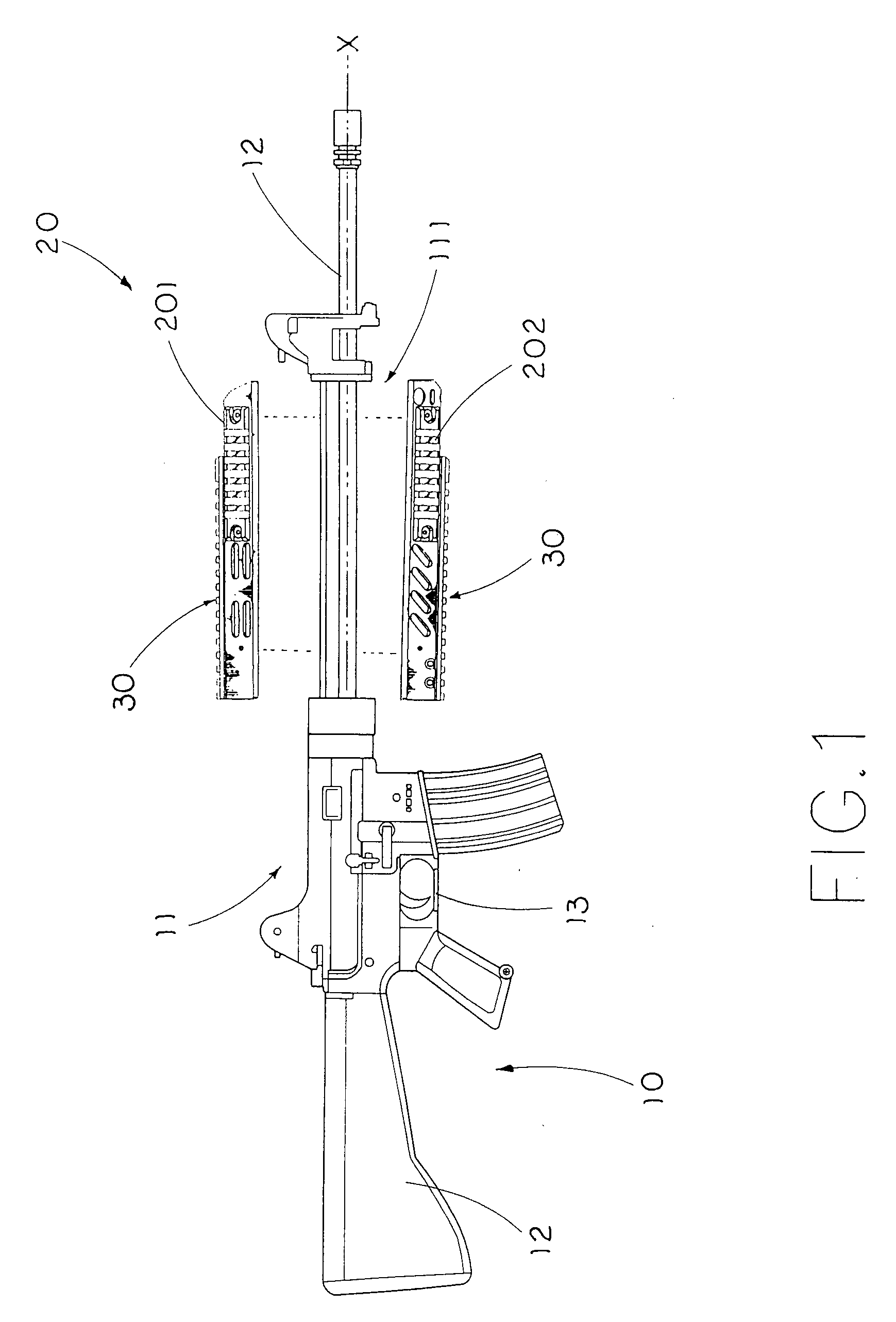
[0022]Referring to FIG. 1 of the drawings, a rail arrangement according to a preferred embodiment of the present invention is illustrated, wherein the rail arrangement is adapted for mounting one or more accessories on the firearm 10.

[0023]Accordingly, the firearm 10 comprises a firing assembly 11 having a frame portion 111 and defining a longitudinal axis X thereat and comprising a barrel 12 supported by the frame portion 111 along the longitudinal axis X. The firearm further comprises a stock 12 extended from a rear end of the firing assembly 11 and a trigger 13 operating the firing assembly 11.

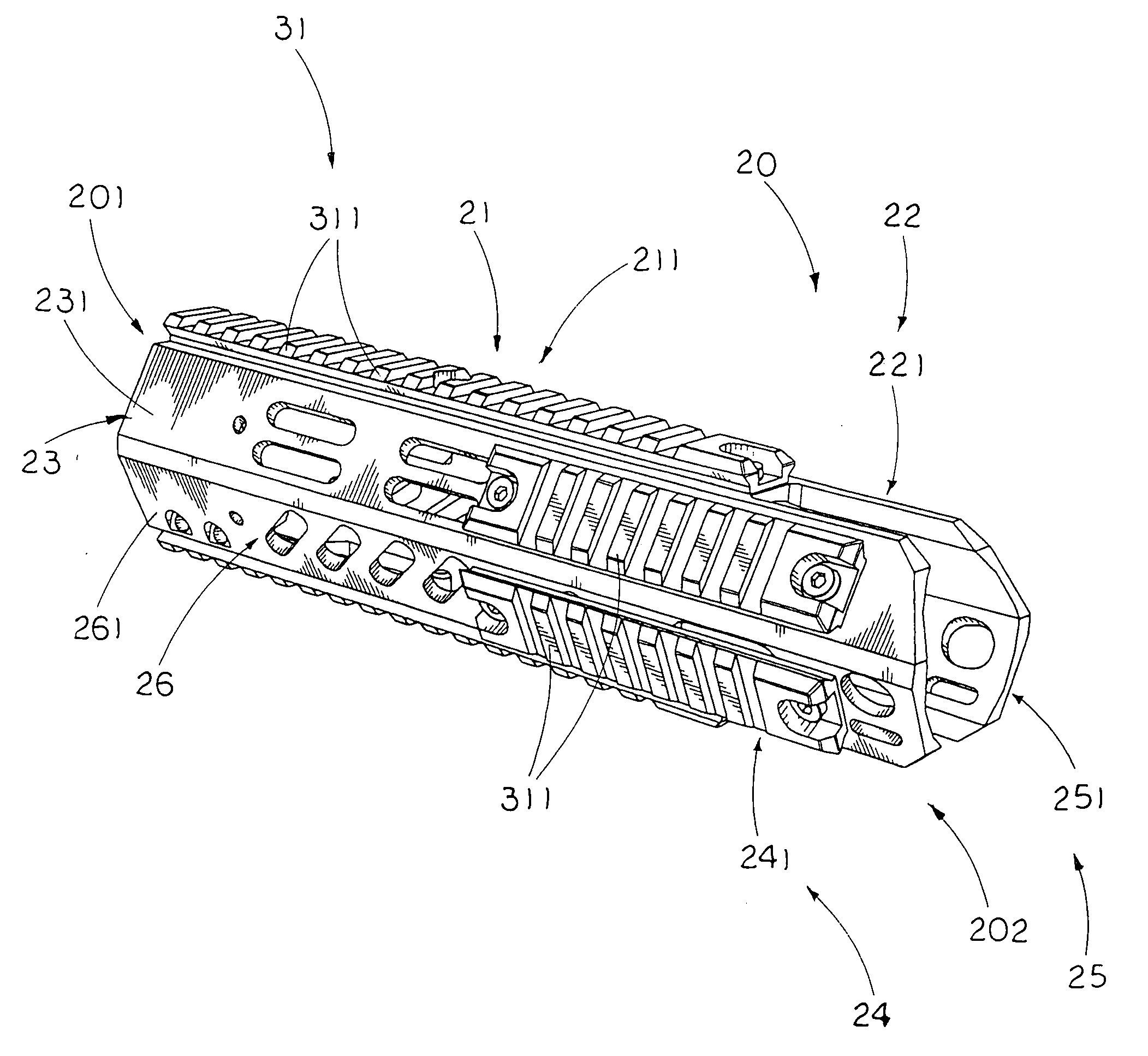
[0024]As shown in FIGS. 1 and 2, the rail arrangement comprises a supporting frame 20 which is adapted for attaching to the frame portion 111 of the firearm along a longitudinal axis X thereof, and a rail system 30 for mounting the accessory on the frame portion 111 of the firearm 10. Accordingly, the accessory can be a long-range telescope sight, a short-range telescope sight, a laser sigh...


PUM


Abstract

A rail arrangement, which is adapted for mounting one or more accessories on a frame portion of a firearm, includes a supporting frame for attaching to the frame portion of the firearm along a longitudinal axis thereof and a rail system. The supporting frame includes a top mounting rail arranged for longitudinally extending on the frame portion, and two angled mounting rails inclinedly and sidewardly extended from the top mounting rail. The rail system includes one or more mounting structures providing of the top mounting rail and two angled mounting rails of the supporting frame for detachably mounting the accessory at one of the top mounting rail and the angled mounting rails of the supporting frame so as to selectively adjust a position of the accessory with respect to the firearm.

Description

BACKGROUND OF THE PRESENT INVENTION[0001]1. Field of Invention[0002]The present invention relates to a firearm, and more particularly to a rail arrangement for a firearm, wherein the rail arrangement provides a plurality of rail surfaces extending longitudinally for the accessory selectively mounting thereat so as to enhance the practical use of the accessory.[0003]2. Description of Related Arts[0004]A conventional firearm generally comprises a firing assembly which includes a barrel and a butt stock extended from a rear end of the firing assembly. For a long gun, such as rifle, the butt stock is adjacent to the shooter's shoulder during firing. Firearm tools or implements, such as an aiming sight for assisting aim by guiding the eye of the shooter to the target, are provided to mount on top of the firing assembly.[0005]Accordingly, the firearm further comprises a mounting rail longitudinally formed a top surface of the firing assembly, wherein the firearm tool is detachably mounted...

Claims


Application Information

Patent Timeline
12 Feb 2009
Publication
US20090038198A1
IPC
F41C27/00
CPC
F41G11/003
Inventors
YU, HERMAN