Eureka AIR delivers breakthrough ideas for toughest innovation challenges, trusted by R&D personnel around the world.

Radio oscillating and radar systems

a radar system and radio oscillating technology, applied in the field of radio oscillating and radar systems, can solve the problems of high cost of oscillation, and achieve the effects of low cost, efficient oscillation sideband wave, and high-performance optical amplifier

Active Publication Date: 2010-08-12
NGK INSULATORS LTD
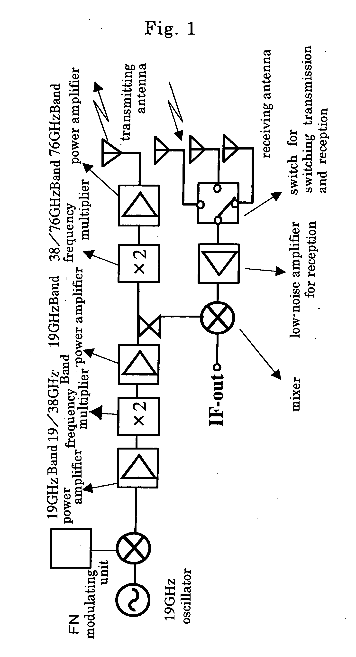
View PDF8 Cites 1 Cited by
  • Summary
  • Abstract
  • Description
  • Claims
  • Application Information

AI Technical Summary

Benefits of technology

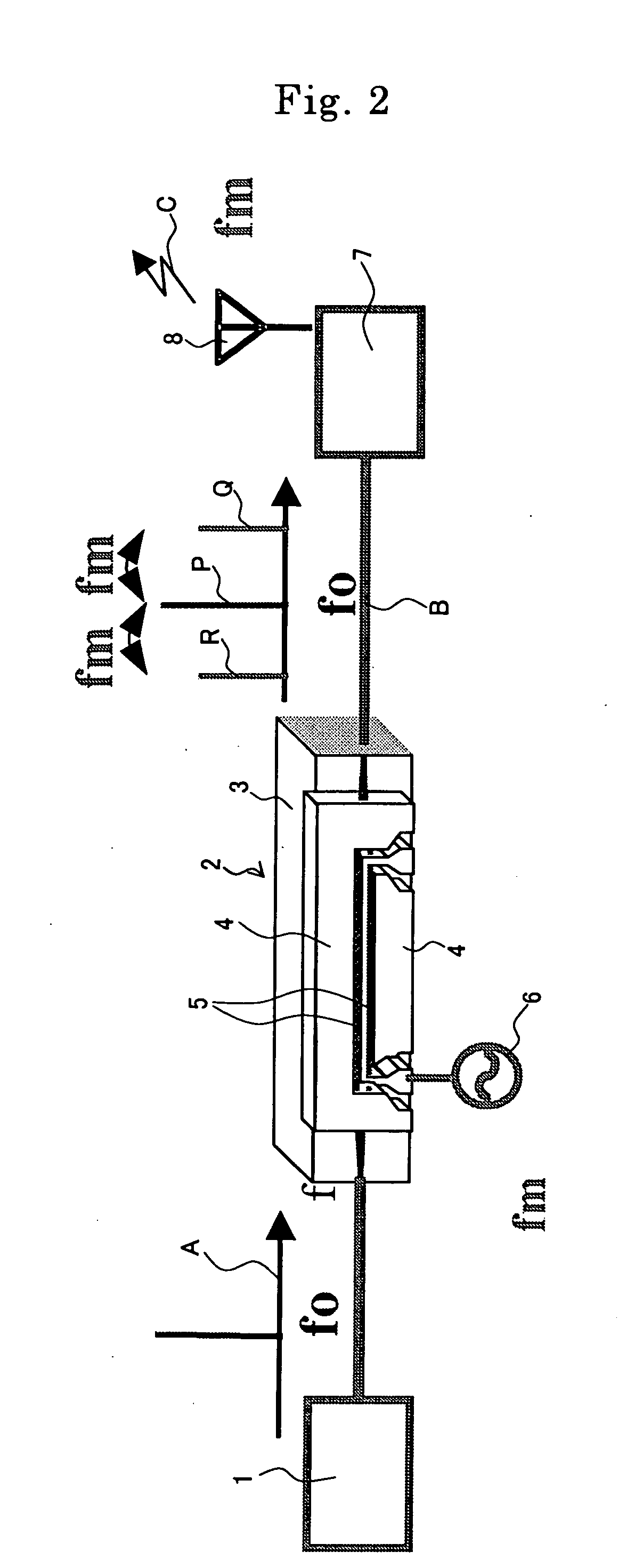
The present invention provides a radio oscillating system that can generate a radio signal with a desired frequency using a mode locking laser system. The system includes an optical modulator, a modulating means, an optical receiver, and a radiating means. The input voltage on the optical modulator is important for generating the desired frequency. The system also includes an optical filter to remove unnecessary signals. The invention aims to improve the practical use of the radio oscillating system by alleviating the necessity of a high-performance and high-reliability amplifier and by providing a more practical solution for the radio oscillating system.

Problems solved by technology

Such oscillation required a high cost due to the above reasons.

Method used


Image

  • Radio oscillating and radar systems
  • Radio oscillating and radar systems
  • Radio oscillating and radar systems

Examples


examples

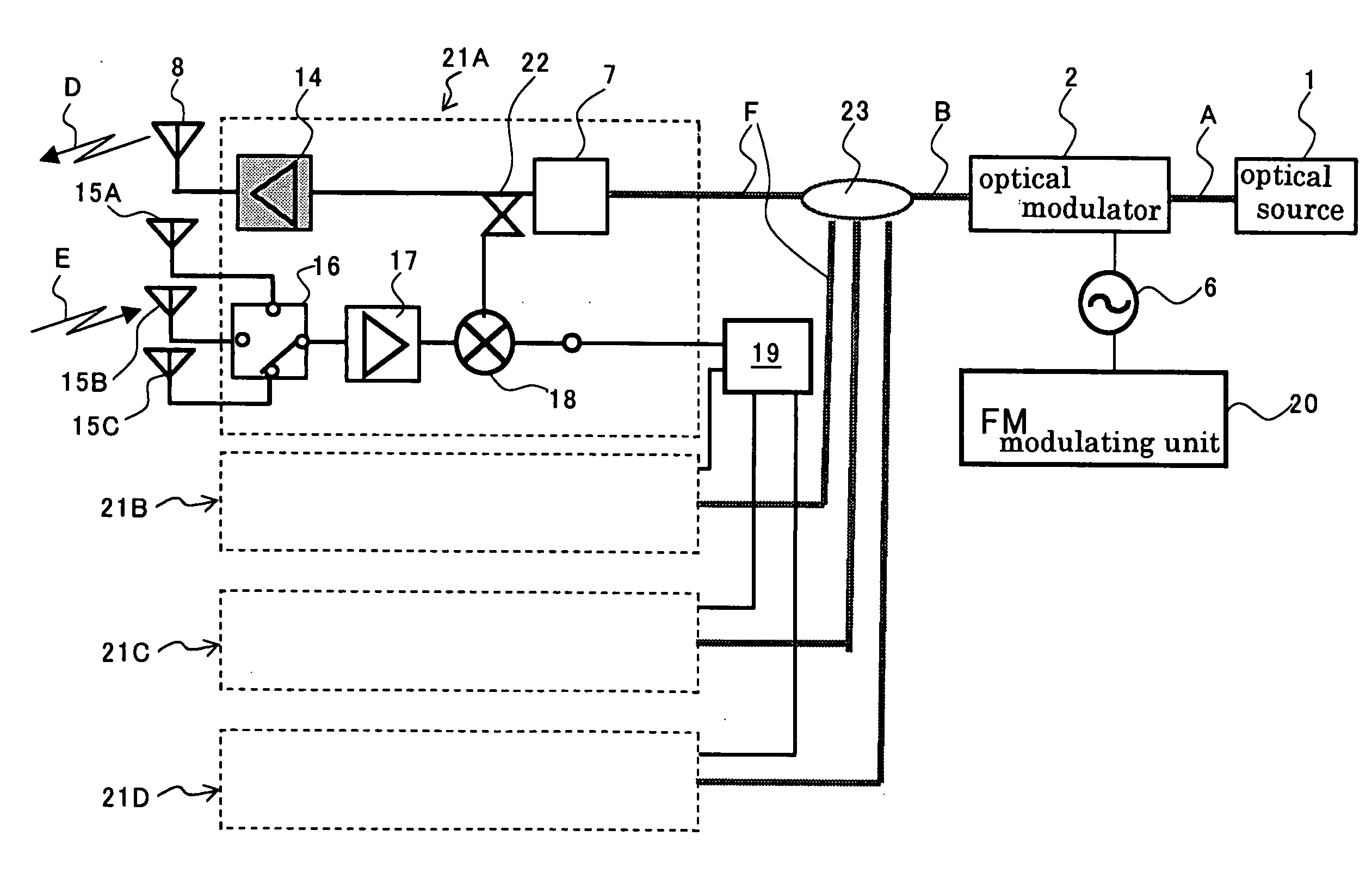
[0147]The radar system was produced using an optical modulator 2 shown in FIG. 20.

[0148]Specifically, Ti-diffusion waveguides 5A, 5B and CPW electrodes 4A, 4B and 4C were formed on a substrate of x-cut lithium niobate. As to the electrode structure, the gaps “G” between the central electrode 4B and ground electrodes 4A 4C were 20 μm, the electrode thickness was 20 μm, and the electrode length was 40 mm. The modulator substrate was adhered to a dummy plate fixed onto a surface plate with a thermoplastic resin, so that the electrode face is oriented downwardly. The substrate was then subjected to horizontal polishing and polishing to a thickness of 6 μm. A plate-shaped reinforcing body 31 of x-cut lithium niobate was adhered to the modulator substrate. The body was subjected to optical polishing at the end face of the optical waveguide and cut into chips. An adhesive having a specific dielectric constant of 4 was used as the adhesive for the fixation and the thickness of the adhesive ...


PUM

PropertyMeasurementUnit
frequencyaaaaaaaaaa
frequency fmaaaaaaaaaa
half-wavelength voltage Vπaaaaaaaaaa

Abstract

It is provided a radio oscillating system for oscillating a radio signal. The system has an optical modulator for oscillation, a modulating means for inputting a modulating signal of a frequency of fm into the optical modulator to modulate a carrier wave so as to interpose sideband waves onto the carrier wave at positions shifted with respect to the frequency of the carrier wave by the frequency “fm”; and an optical receiver for oscillation for receiving beam from the optical modulator and converting the beam into an electrical signal. The system further has a radiating means for radiating radio signal of a frequency of 2 fm based on the electrical signal. An input voltage Vp−p applied on the optical modulator is 1.0 times or more and 1.99 times or less of a half-wavelength voltage Vπ of the optical modulator.

Description

[0001]This application claims the benefit of Japanese Patent Application P 2005-270612 filed on Sep. 16, 2005, the entirety of which is incorporated by reference.BACKGROUND OF THE INVENTION[0002]1. Field of the Invention[0003]The present invention relates to radio oscillating and radar systems.[0004]2. Related Art Statement[0005]In Intelligent Transport Systems (ITS), it has been widely demanded a radar system utilizing radio wave such as an on-vehicle radar system. It has recently been developed, and partly commercialized, a radar system utilizing radio wave of 76 GHz band.[0006]An on-vehicle radar system is provided on the front side of a vehicle body so that it can measure the direction, distance and relative velocity of the car with respect to one running ahead of the car to function as a sensor for preventing the car accident. It will be strongly demanded an auto cruise system (ACC) controlling the speed of a vehicle and assuring the safety distance between cars. It is thus req...

Claims


Application Information

Patent Timeline
Patent Type & Authority Applications(United States)
IPC IPC(8): G01S13/34G01S7/282G01S13/931G02F1/035
CPCG01S7/352G01S13/34G01S13/87G01S2013/9325G02F1/0516G01S2013/9375G01S2013/9321G01S13/931G01S2013/93271G02F2/02
Inventor KONDO, JUNGOMITOMI, OSAMUAOKI, KENJIIWATA, YUICHIEJIRI, TETSUYA
Owner NGK INSULATORS LTD
Why Eureka
Eureka Blog
Learn More