

Magnetic resonance device
- Summary
- Abstract
- Description
- Claims
- Application Information
AI Technical Summary
Benefits of technology
Problems solved by technology
Method used
Image

Examples
Example
DETAILED DESCRIPTION OF THE DRAWINGS
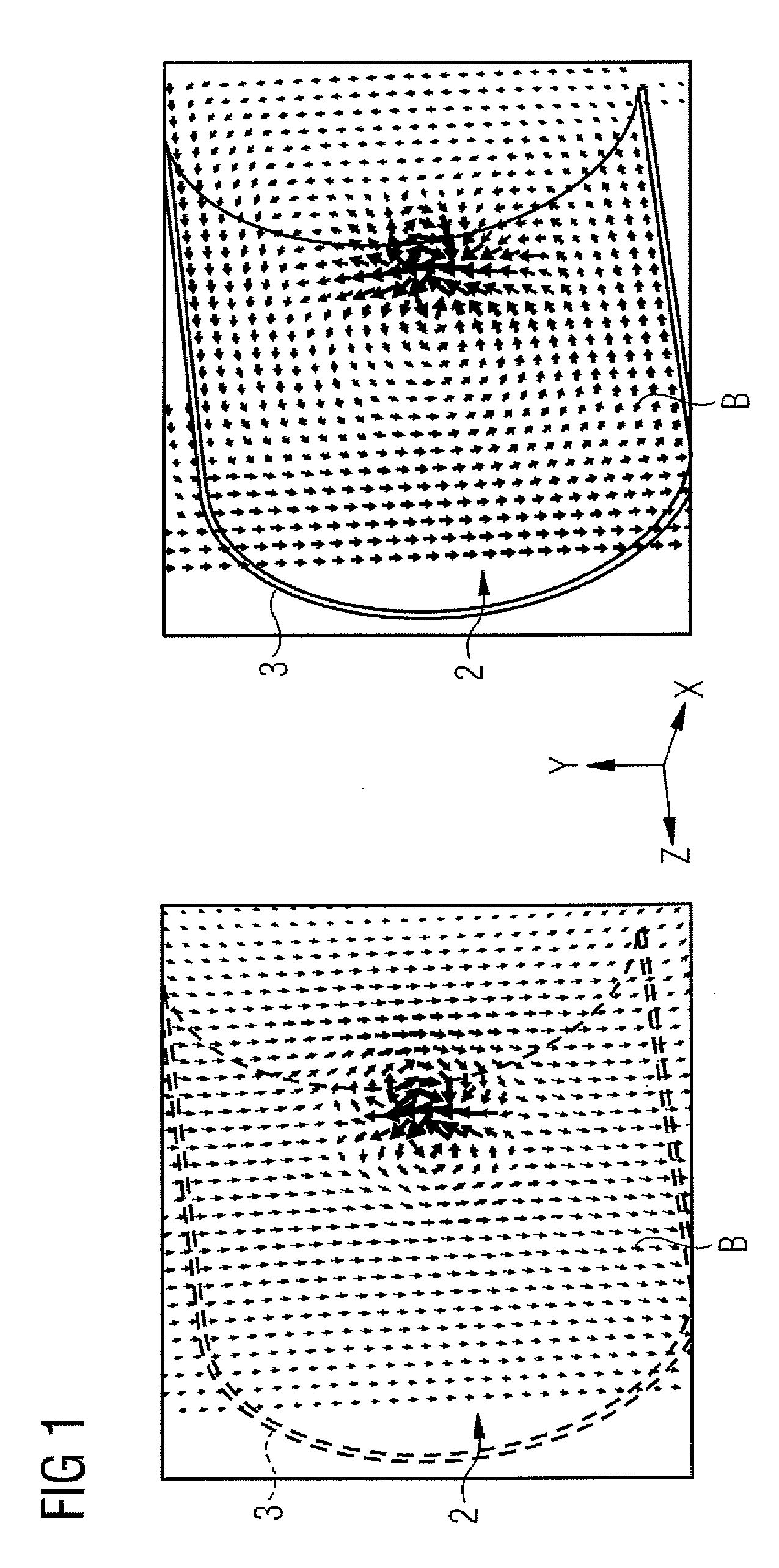
[0038]FIG. 1 shows the result of simulations of a high-frequency magnetic field distribution B that occurs when a simple magnetic high-frequency dipole generates an oscillating field with a frequency of 300 MHz in a 7 Tesla magnetic field in a measuring chamber 2 of a magnetic resonance device. This corresponds to the transmitted magnetic resonance signal of a water proton in a 7 Tesla magnetic field. The diagrams in FIG. 1 each show one layer of the magnetic field distribution within a layer running parallel to the z-axis of the magnetic resonance device. Disposed on the right is a half shell of a high-frequency shield 3 disposed in a circular manner around the measuring chamber 2 (e.g., represented in FIG. 1 by a simple semi-cylindrical conductor surface). Shown on the left side with a broken line is the position of the high-frequency shield for comparison purposes. Of interest in these simulations is the behavior of the magnetic field lines in ...
PUM
 Abstract
Description
Claims
Application Information