Connector

a technology of connecting rods and connectors, applied in the direction of coupling device connections, connection contact member materials, coupling protective earth/shielding arrangements, etc., can solve the problems of slow computer processing speed, adverse influence on signal transmission speed and stability at the connector, and reduce data transmission speed. , to achieve the effect of more rapid and stable transmission of signals through the connector

Active Publication Date: 2005-05-05
ALL BEST ELECTRONICS
View PDF6 Cites 11 Cited by
  • Summary
  • Abstract
  • Description
  • Claims
  • Application Information

AI Technical Summary

Benefits of technology

[0012] With the above arrangements, terminals of the connector are individually isolated from one another, so that the terminals do not mutually interfere with one another during signal transmission at high speed.

Problems solved by technology

While signals are transmitted via the connectors at high speed, the terminals of the connectors inevitably mutually interfere with one another due to a magnetic effect from current, and might be interfered by external interference sources to result in reduced data transmission speed and slow computer processing speed.
However, electromagnetic interference (EMI) tends to occur at the terminals in the plastic core that are not covered with the cond

Method used


Image

  • Connector
  • Connector
  • Connector

Examples


first embodiment

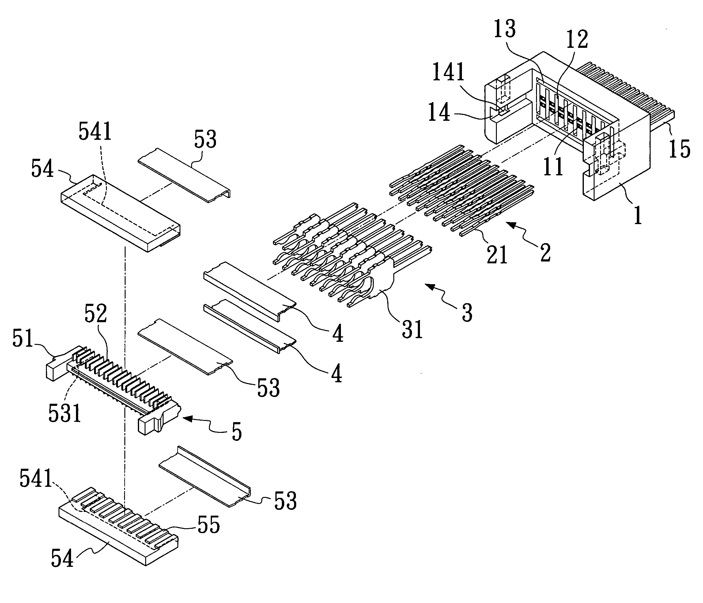
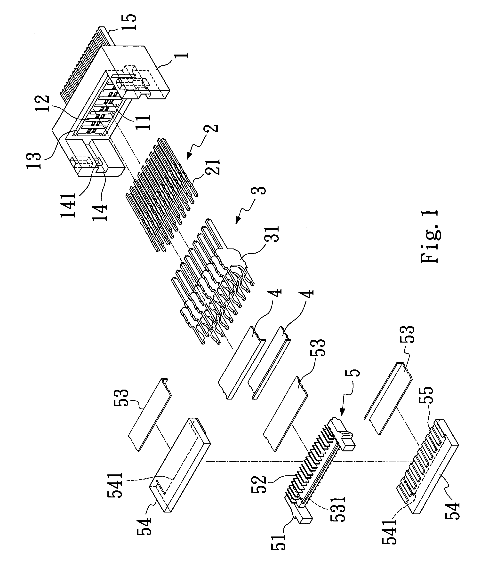
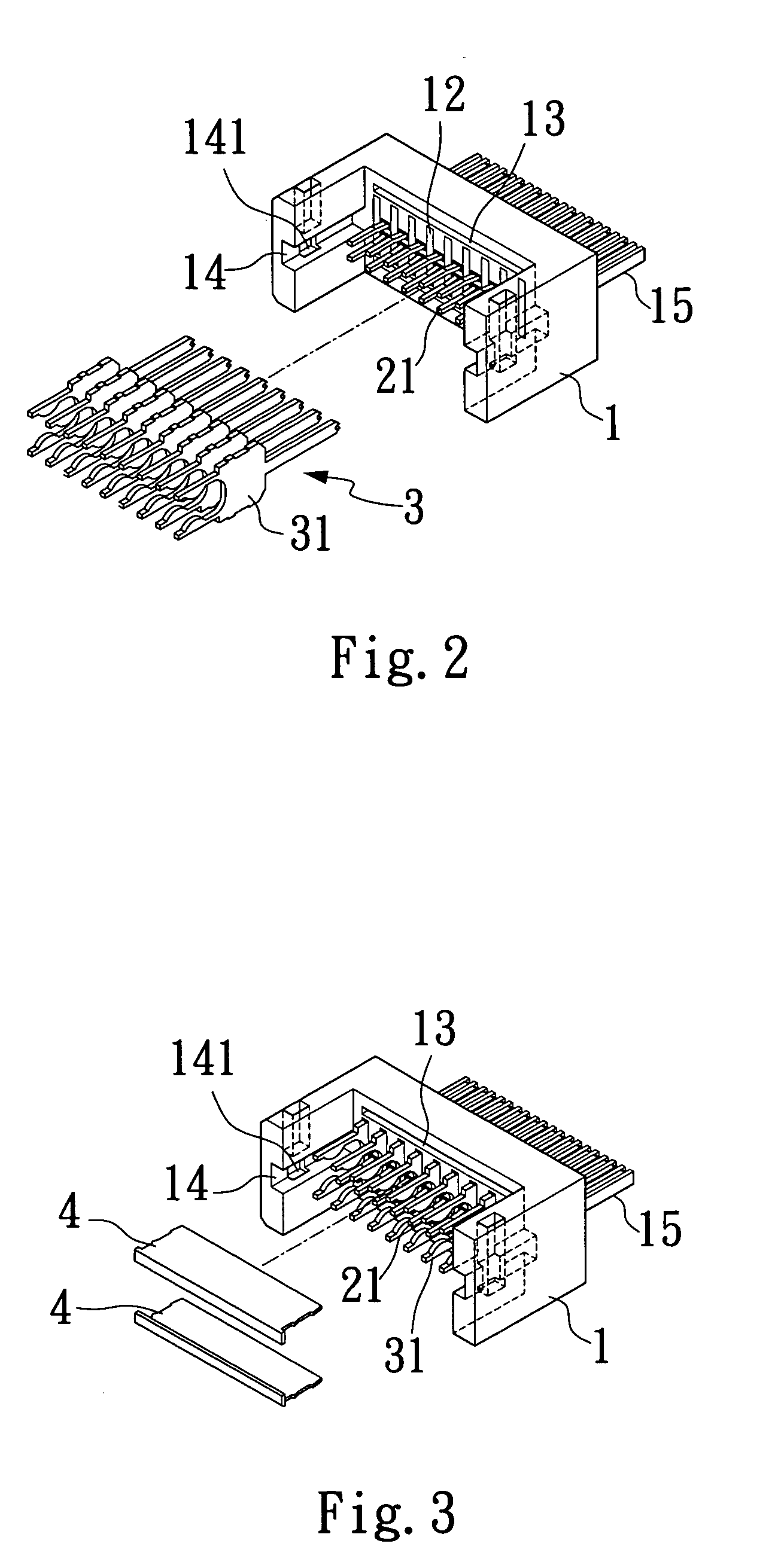
[0037] Please refer to FIG. 1 that is an exploded perspective view of a connector according to the present invention, and to FIGS. 2 and 3 that are partially assembled perspective views of the connector of FIG. 1. As shown, the connector mainly includes a plastic core 1, a set of terminals 2, a set of first isolating plates 3, two first conductive plates 4, and an insertion element 5.

[0038] The plastic core 1 is provided on an inner central portion at upper and lower sides thereof with upper and lower receiving slots 13, and at an area of the inner central portion between the upper and lower receiving slots 13 with a plurality of alternately arranged terminal slots 11 and isolating plate slots 12. The terminal slots 11 are divided into an upper and a lower row. The plastic core 1 is also provided at each of two lateral inner sides with a slide way 14, in which a retaining slot 141 is provided at a predetermined position. A connecting head 15 is externally provided at a front end of ...

second embodiment

[0053]FIG. 13 is a cross sectional view taken along line C-C′ of FIG. 12. Please refer to FIG. 13. As shown, in the fully assembled connector according to the present invention, the first isolating plates 861 together form a plurality of isolated cells that separate and isolate individual terminals 851 from one another, and the two first conductive plates 87 eliminate the interferences between the terminals 851 and from external environments, so that signals may be transmitted via the connector more quickly and stably. Moreover, with the engagement of the central slits 871 on the first conductive plates 87 with the central ribs 841 in the upper and lower receiving slots 84 on the plastic core 8, the central slits 871 on the second conductive plate 87 with the central rib 882 in the central receiving slot 881 of the insertion element 88, and the central slits 871 on the third conductive plates 87 with the central ribs 931 in transverse recesses 93 of the outer covers 91, the first, t...

third embodiment

[0060] The outer covers 112 are located at upper and lower sides of the insertion element 109 to enclose the insertion element 109 in the plastic core 10. Each of the outer covers 112 is provided at an inner side with a plurality of isolating ribs 113 corresponding to and covering spaces between the second isolating plates 111 on the insertion element 109. Each of the outer covers 112 is also internally provided at a central position with a transverse recess 114 having a plurality of equally spaced ribs 1141, into which a third conductive plate 108 having a plurality of equally spaced slits 1081 is received with the slits 1081 engaged with the ribs 1141 and thereby firmly hold the third conductive plate 108 in the transverse recess 114. The third conductive plates 108 received in the two outer covers 112 are in contact with the first conductive plates 108 received in the plastic core 10. Finally, terminals 1151 of two signal cables 115 are separately connected to the terminals 1061 ...


PUM


Abstract

A connector includes a plastic core having upper and lower receiving slots, upper and lower rows of terminal slots, and isolating plate slots provided at a central portion, two slide ways provided at two lateral inner sides, and a connecting head provided at a front end thereof; a plurality of terminals located in the terminal slots; a plurality of isolating plates located in the isolating plate slots; two first conductive plates located in the upper and lower receiving slots; an insertion element having two lateral ends slidably engaged with the slide ways on the plastic core, and having a central receiving slot for receiving a second conductive plate therein; and two outer covers enclosing the insertion element in the plastic core, and having two third conductive plates received in receiving recesses provided thereon to contact with the first conductive plates.

Description

FIELD OF THE INVENTION [0001] The present invention relates to a connector, and more particularly to an improved connector that includes individually isolated terminals to avoid mutual interferences between the terminals during transmission of signals at high speed, and to isolate the terminals from external electromagnetic interference (EMI) or crosstalk, so as to enable quicker and more stable transmission of signals via the connector. BACKGROUND OF THE INVENTION [0002] With the increasingly developed technologies, the applications of computer are also diversified. Various kinds of peripheral products for computers are developed and introduced into markets at extremely quick speed to satisfy the consumers' demands. Under the concept of Time is Money in the current industrial society, it is necessary for a computer to process data as quick as possible. Therefore, the central processing unit (CPU) of a computer has been developed to have extremely high operation speed. Similarly, wh...

Claims


Application Information

Patent Timeline
IPC IPC(8): H01R9/03H01R13/424H01R13/658H01R13/66
CPCH01R9/032H01R13/424H01R13/6658H01R13/6585H01R2107/00H01R24/62H01R12/721H01R13/65912
Inventor YANG, RICK
Owner ALL BEST ELECTRONICS
Why Eureka
Try Eureka