Fly-cutting head, system and method, and tooling and sheeting produced therewith

a technology of cutting head and cutting head, which is applied in the direction of turning machine accessories, process and machine control, program control, etc., can solve the problems of inability to use a new microreplication tool, inability to create a new tool, and inability to thread-cut a steel roll using a conventional cutting tool for weeks of continuous work

a technology of cutting head and cutting head, which is applied in the direction of turning machine accessories, process and machine control, program control, etc., can solve the problems of inability to use a new microreplication tool, inability to create a new tool, and inability to thread-cut a steel roll using a conventional cutting tool for weeks of continuous work

US20090038450A1Active Publication Date: 2009-02-123M INNOVATIVE PROPERTIES CO

Image

  • Fly-cutting head, system and method, and tooling and sheeting produced therewith
  • Fly-cutting head, system and method, and tooling and sheeting produced therewith
  • Fly-cutting head, system and method, and tooling and sheeting produced therewith

Examples


Embodiment Construction

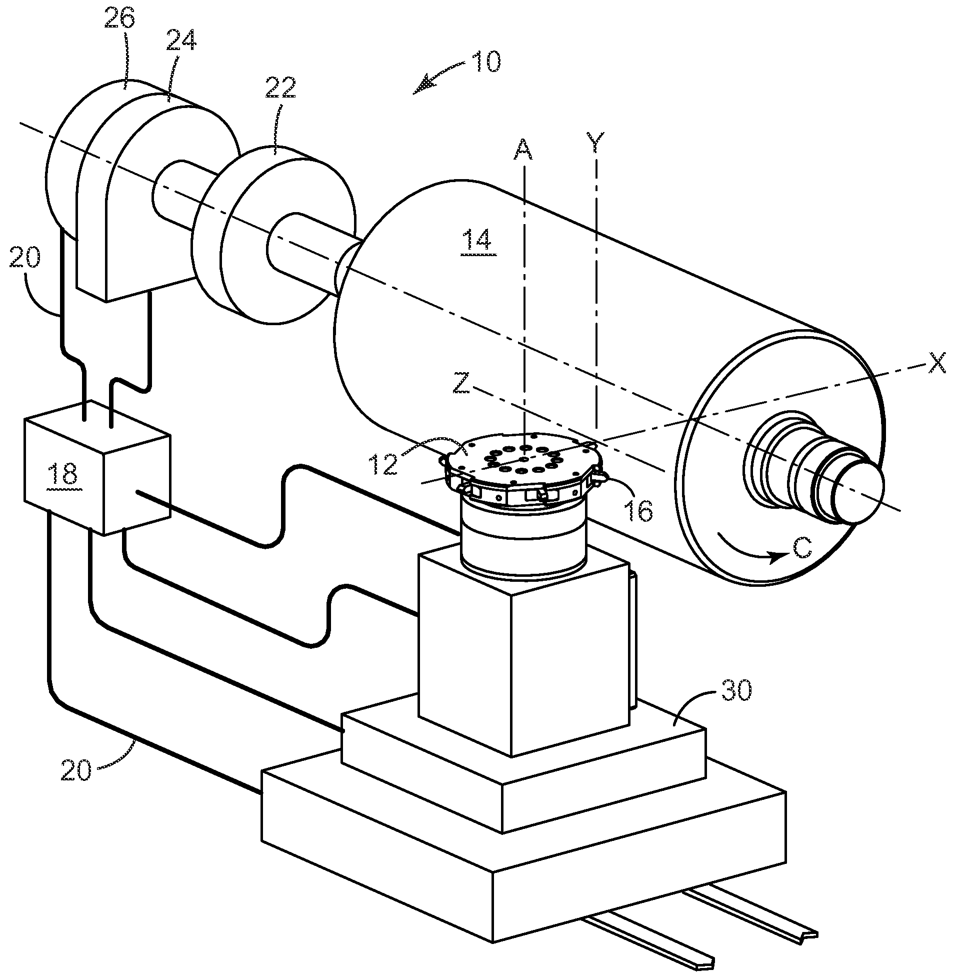
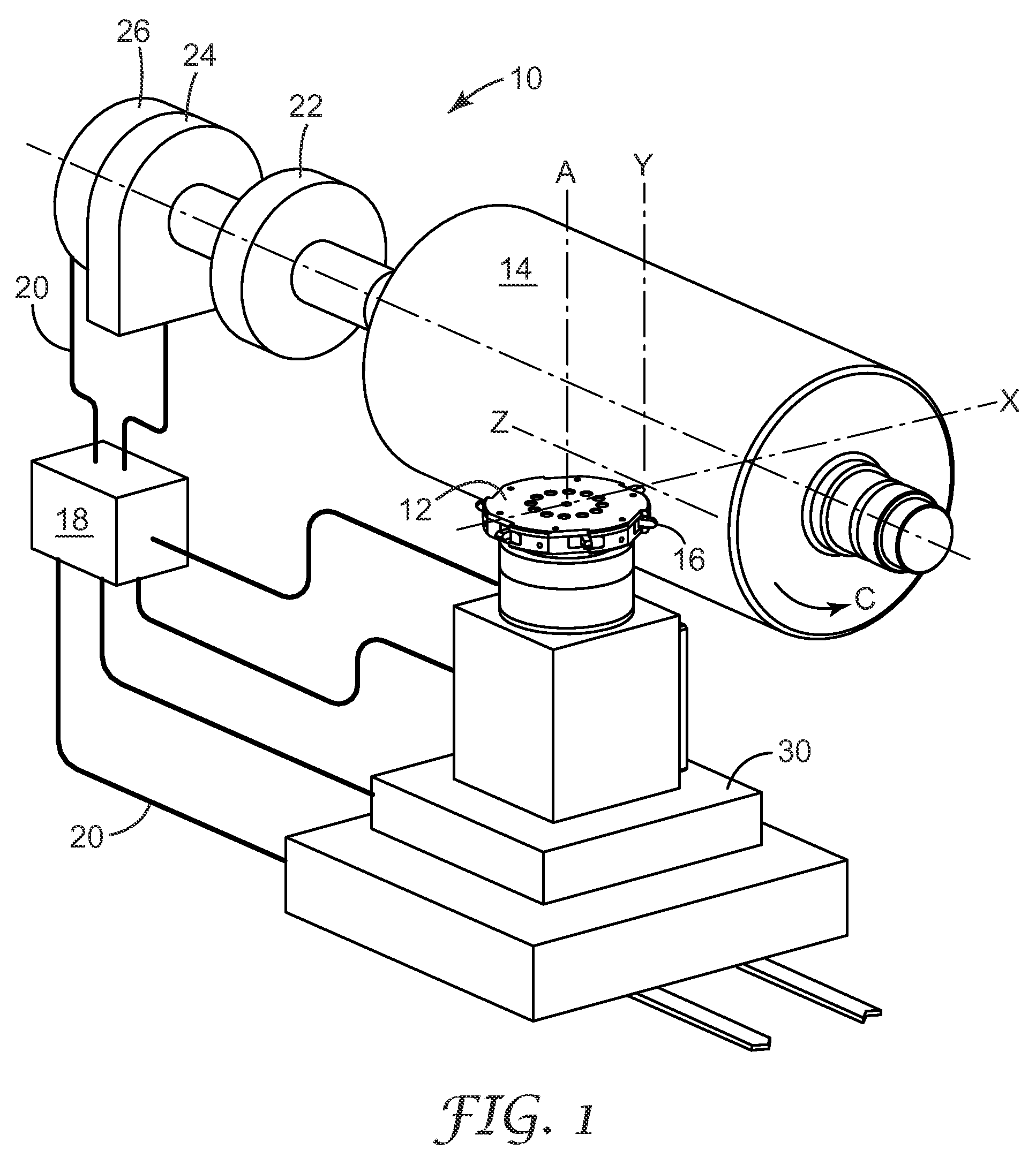
[0027]The present invention includes several embodiments, including fly-cutting heads or systems with certain dynamically controllable features such as control of the cutting radius, and other devices, systems, and methods as described in detail below. These devices, systems, and methods are useful in making microreplication tools also according to the present invention, and those tools can in turn be used to create microstructured surfaces such as microstructured polymeric sheeting, also according to the present invention.

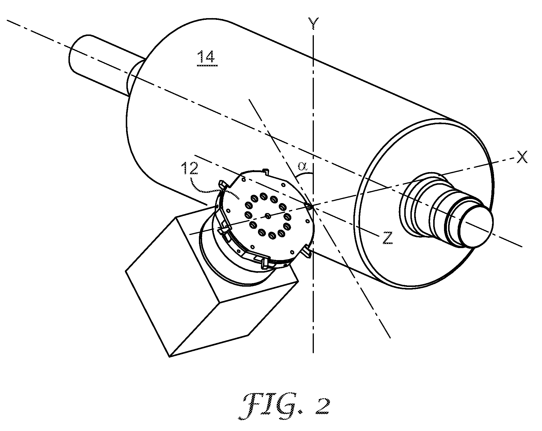
[0028]Fly-cutting typically refers to the use of a cutting element, such as a diamond, that is mounted on or incorporated into a shank or tool holder that is positioned at the periphery of a rotatable head or hub, which is then positioned relative to the surface of the workpiece into which grooves or other features are to be machined. Fly-cutting is typically a discontinuous cutting operation, meaning that each cutting element is in contact with the workpiece for ...


PUM

PropertyMeasurementUnit
Angleaaaaaaaaaa
Angleaaaaaaaaaa
Radiusaaaaaaaaaa

Abstract

A fly-cutting system is disclosed, and in particular one that comprises a dynamically-controllable actuator for controlling the position, orientation, or both position and orientation of a cutting element carried by a fly-cutting head. In certain embodiments, the actuator can adjust the position or orientation of a cutting element, or both, hundreds or thousands of times per second, enabling precise control over the shape of features formed by the cutting element in a surface of a workpiece.

Description

RELATED APPLICATION[0001]This application is generally related to the subject matter of U.S. Patent Application Ser. No. ______, entitled “Fly-Cutting System and Method, and Related Tooling and Articles,” Attorney file number 63327US002, which was commonly assigned to the assignee of the present invention, was filed on the same date as the present application, and is incorporated by reference herein.TECHNICAL FIELD[0002]A fly-cutting apparatus is disclosed of the type used to create grooves or similar features in a workpiece to form a microreplication tool, as well as a system and method for using such an apparatus, microreplication tools made thereby, and sheeting produced using a microreplication tool so made.BACKGROUND OF THE INVENTION[0003]Precision-engineered surfaces, such as polymeric optical films that include linear prisms or cube-corner prisms to control and direct light, are useful in a variety of applications. For example, cube-corner sheeting can be adapted to reflect l...

Claims


Application Information

Patent Timeline
12 Feb 2009
Publication
US20090038450A1
IPC
B23B27/00
CPC
B23B29/125; B23B2260/108; B23C3/34; B23C5/08; B23C2226/125; Y10T82/10; B23C2226/315; Y10T428/24479
Inventors
CAMPBELL, ALAN B.; EHNES, DALE L.