Heat Exchanger

a technology of heat exchanger and heat exchanger plate, which is applied in the direction of indirect heat exchanger, laminated elements, lighting and heating apparatus, etc., can solve the problems of inability to use heat exchanger and relatively large edges, and achieve the effect of reducing time required, preventing mutual displacement of stacked plates, and quick and cost-effective manufacturing process

Inactive Publication Date: 2009-02-12
ALFA LAVAL CORP AB
View PDF8 Cites 4 Cited by
  • Summary
  • Abstract
  • Description
  • Claims
  • Application Information

AI Technical Summary

Benefits of technology

[0004]A further disadvantage of the invention according to Japanese patent specification JP 09-113170 is that the locating means only prevents movement of the plates transversely to the direction of the edge portion. Two plates placed against one another are not prevented from moving in the direction of the plate longitudinally with the edge portions. The result during soldering of the plates is that the plates might shift in a longitudinal direction relative to one another, rendering the heat exchanger impossible to use.
[0005]A heat transfer plate with locating means comprises an edge portion which extends round the periphery of the plate, and a heat transfer surface which is surrounded by the edge portion. The heat transfer surface normally exhibits a pattern of crests and valleys. The crests and valleys are situated within a first (upper) plane and a second (lower) plane. The lateral mid-portion of the heat transfer surface is in a normal plane situated between the first and second planes. The heat transfer plate is stacked on top of a plate which is similar but oriented differently in a plate stack in a heat exchanger. Flow channels which accommodate different media are formed between the plates in the plate stack. During operation there is temperature exchange between the media in mutually adjacent channels.
[0006]An object of the present invention is to provide a heat transfer plate for a permanently connected heat exchanger comprising a unflanged plate stack which can be set up during manufacture without the plate stack having to be supported externally by walls or guiding elements to prevent mutual displacement of the stacked plates during handling relating to the soldering process.
[0007]An object of the present invention is to provide a heat transfer plate for a permanently connected heat exchanger comprising a unflanged plate stack whereby the plates in the plate stack cannot rotate relative to one another during the manufacturing process.
[0008]An object of the present invention is to provide a heat exchanger which is made up of heat transfer plates stacked on, and permanently connected to, one another.
[0009]A further object of the present invention is to provide a design which makes it possible to reduce the time required for making heat exchanger plate stacks so that the manufacturing process will be quick and cost-effective.

Problems solved by technology

The disadvantage of having locating means situated in edge portions is that the edges will be relatively large.
A further disadvantage of the invention according to Japanese patent specification JP 09-113170 is that the locating means only prevents movement of the plates transversely to the direction of the edge portion.
The result during soldering of the plates is that the plates might shift in a longitudinal direction relative to one another, rendering the heat exchanger impossible to use.

Method used


Image

  • Heat Exchanger
  • Heat Exchanger

Examples


Embodiment Construction

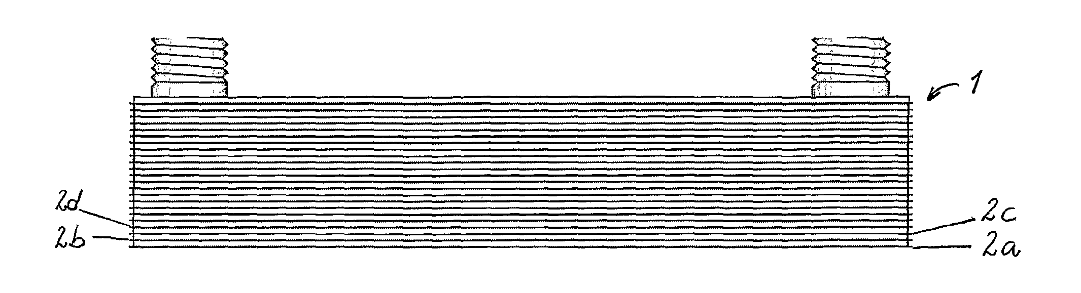
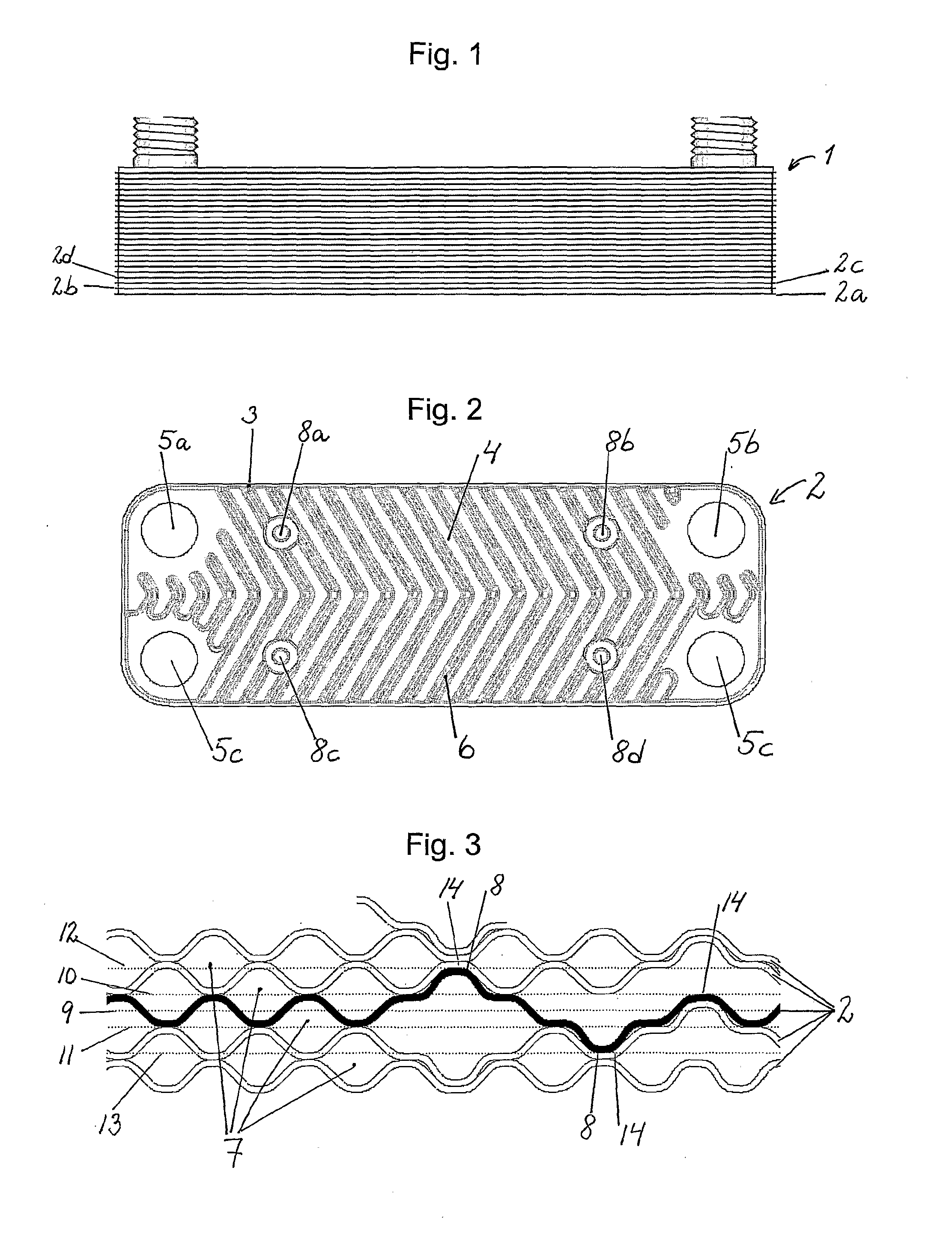
[0027]FIG. 1 depicts a heat exchanger with a plate stack (1) comprising unflanged heat transfer plates stacked on top of one another. In the ensuing text, the expression “heat transfer plate” is synonymous with “plate”. FIG. 2 depicts a plate (2). The plate comprises an edge portion (3) which extends round the periphery of the plate (2). A heat transfer surface (4) is situated within the edge portion (3). At each corner of the plate, a port (5a-d) is provided for inflow and outflow of medium. In the preferred embodiment, the heat transfer plate has a pattern (6) for optimising the heat transfer in the heat exchanger. The pattern (6) comprises crests and valleys, which on mutually adjacent plates abut against one another locally so as to constitute contact points which in a known manner are used for connecting the plates to one another during the soldering together of the heat exchanger. Flow channels (7, see FIG. 3) are formed between mutually adjacent plates (2) in a plate stack (1...


PUM


Abstract

This relates to a heat transfer plate (2) with locating means (8) and adapted to being stacked in a plate stack, and a heat exchanger including such plates (2). The plate (2) has a patterned heat transfer surface, an edge portion, ports, locating means (8) and accommodating means (14). Locating means (8) in the form of nibs (8) is situated on the heat transfer surface of the plate. The nibs (8) are between two planes (10 and 12) situated above the heat transfer surface pattern. In the plate stack, between two mutually adjacent plates (2), the nibs (8) fit into accommodating means (14) on an adjacent plate (2), which accommodating means (14) are disposed in the latter's heat transfer surface. Two mutually adjacent plates (2) in the plate stack together have two nibs (8) and two accommodating means (14) which fit into one another and thereby fix the plates (2) relative to one another so that the plates cannot shear or rotate relative to one another. This means that plates (2) need not have any so-called locating flanges for positioning them in a plate stack.

Description

FIELD OF THE INVENTION[0001]The present invention relates to a heat exchanger according to the preamble of claim 1.[0002]Permanently connected heat exchangers are traditionally made up of a number of heat transfer plates forming a plate stack. The soldering process involves the plate stack being placed in a furnace whereby the solder connects the plates to one another. During the handling operations relating to the soldering it may easily happen that unflanged plates lying on one another become mutually displaced. To prevent this, it is usual for fixtures to be used during heat exchanger manufacture. A usual such means is that the plates are placed within so-called support pins which therefore prevent the plates from shifting sideways.BACKGROUND TO THE INVENTION[0003]Japanese patent specification JP 09-113170 refers to a heat transfer plate with locating means in the form of pressed ridges situated in its edge portion. During plate stacking, the locating means engages mechanically w...

Claims


Application Information

Patent Timeline
Patent Type & Authority Applications(United States)
IPC IPC(8): F28F3/00
CPCF28D9/005F28F2280/04F28F3/046F28D9/00F28F3/08F28D9/0037
Inventor LARSSON, ROLANDDRAKARVE, KERSTIN
Owner ALFA LAVAL CORP AB
Why Eureka
Try Eureka