

Optical fiber lighting apparatus
a technology of optical fiber and lighting apparatus, applied in the direction of fibre light guides, instruments, applications, etc., can solve the problems of poor light guide efficiency of the system and difficulty in obtaining sufficient illumination ligh
- Summary
- Abstract
- Description
- Claims
- Application Information
AI Technical Summary
Benefits of technology
Problems solved by technology
Method used
Image

Examples
first embodiment
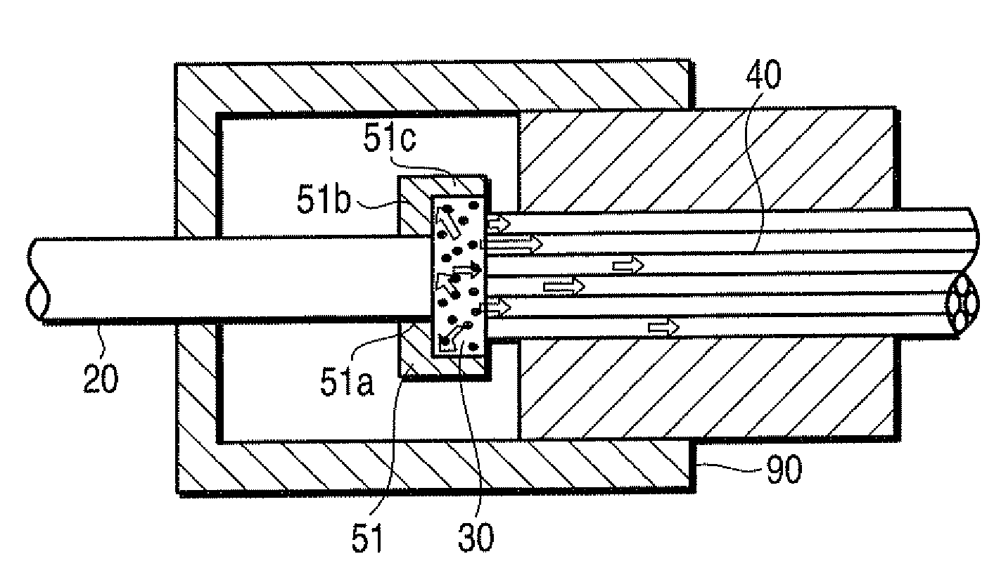
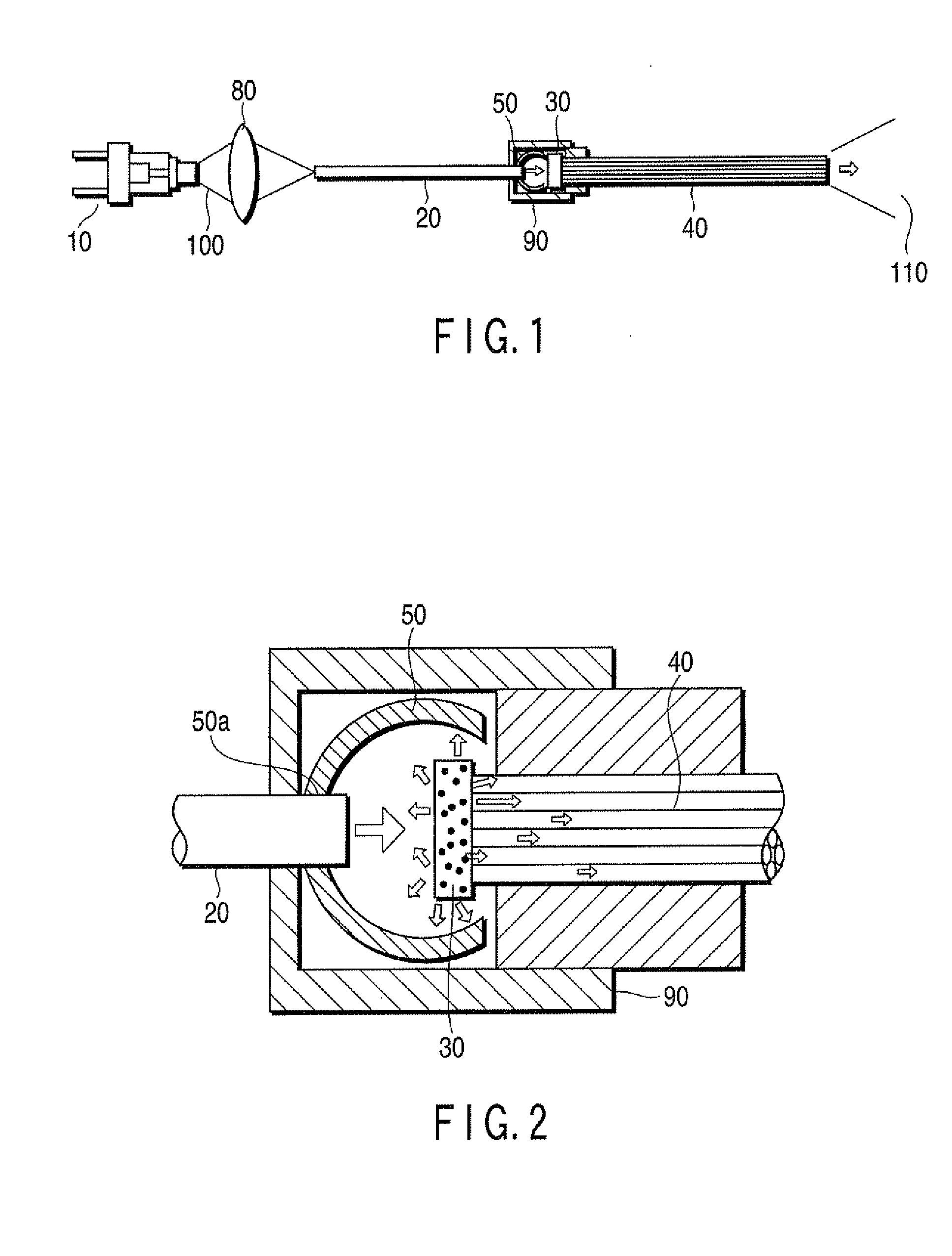
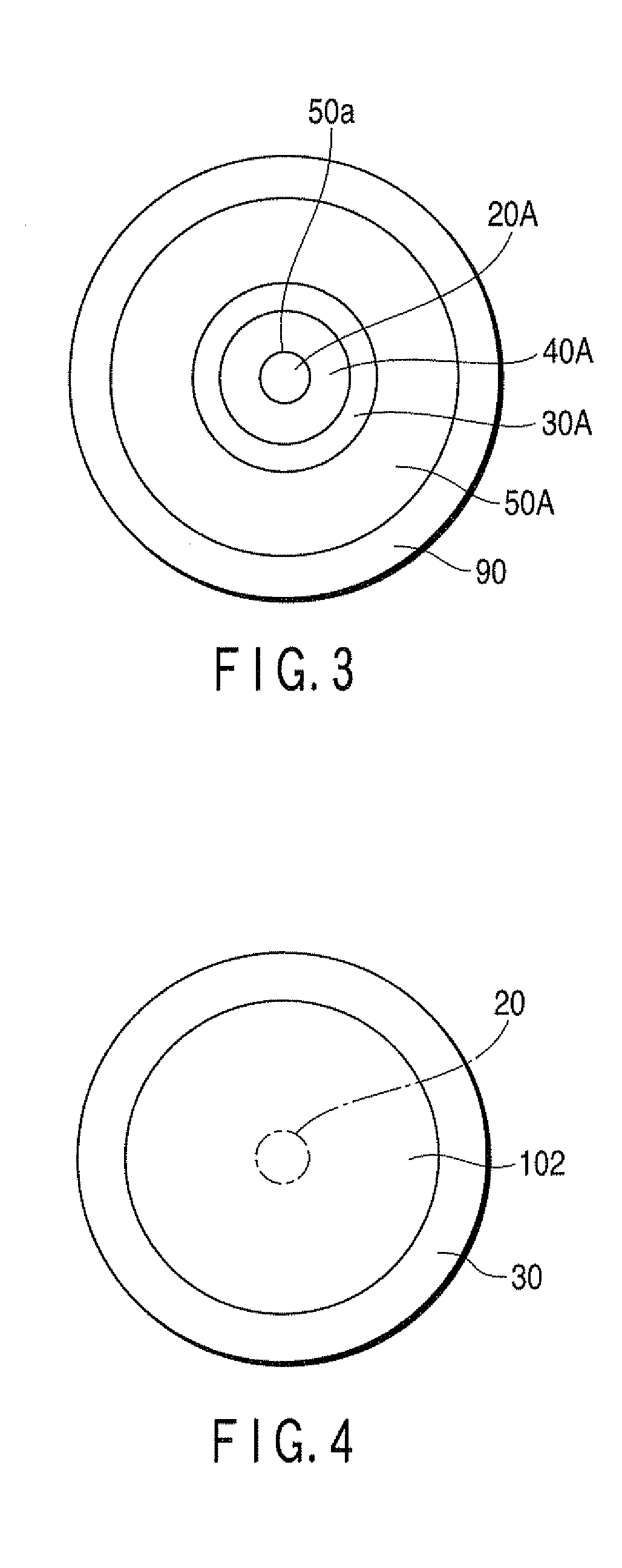
[0026]FIG. 1 shows an optical fiber lighting apparatus according to the first embodiment of the present invention. As shown in FIG. 1, the optical fiber lighting apparatus includes a semiconductor laser 10 as an exciting light source that emits exciting light 100, a single fiber 20 as the first optical fiber that guides the exciting light 100 emitted from the semiconductor laser 10, a phosphor unit 30 as a wavelength conversion unit that receives the exciting light 100 exiting from the single fiber 20 to generate fluorescence as wavelength-converted light having a wavelength different from the exciting light 100, and a fiber bundle 40 as the second optical fiber that guides at least part of the wavelength-converted light, i.e., the fluorescence, generated from the phosphor unit 30. The semiconductor laser 10 may be, for example, a violet semiconductor laser. The laser to be used is not limited to this, and another type of semiconductor laser can be used. The phosphor unit 30 include...
second embodiment
[0045]FIG. 9 shows an optical fiber lighting apparatus according to the second embodiment of the present invention. The optical fiber lighting apparatus of this embodiment has the same basic structure as that in the first embodiment. As shown in FIG. 9, however, this apparatus includes an LED 12 in place of the semiconductor laser 10 as an exciting light source and a fiber bundle 24 in place of the single fiber 20 as the first optical fiber. Using the LED 12 as an exciting light source can simultaneously achieve low cost and eye safety. In addition, this can simplify the system by eliminating the necessity of a feedback circuit for optical outputs. Furthermore, using the fiber bundle 24 as the first optical fiber that guides exciting light can efficiently guide LED light and apply it to a phosphor unit 30.
[0046]In this arrangement, at the exit end of the fiber bundle 24, exciting light exits from each single fiber constituting the fiber bundle 24. In this case, an optical axis at th...
third embodiment
[0048]FIG. 10 shows an optical fiber lighting apparatus according to the third embodiment of the present invention. The optical fiber lighting apparatus according to this embodiment has the same basic structure as that of the first embodiment. As shown in FIG. 10, however, this apparatus includes, in place of the semiconductor laser 10, semiconductor lasers 10-1, 10-2, and 10-3 that respectively emit exciting light beams. The apparatus also includes, in place of the single fiber 20, single fibers 20-1, 20-2, and 20-3 that respectively guide exciting light beams emitted from the semiconductor lasers 10-1, 10-2, and 10-3. The apparatus further includes, in place of the phosphor unit 30, phosphor units 30-1, 30-2, and 30-3 that respectively receive the exciting light beams exiting from the single fibers 20-1, 20-2, and 20-3 to generate wavelength-converted light beams having different wavelengths. The number of phosphor units 30-1, 30-2, and 30-3 is the same as that of single fibers 20...
PUM
 Abstract
Description
Claims
Application Information