Mobile communication system, base station, and inter-cell interference reduction method

a technology of inter-cell interference and mobile communication system, which is applied in the direction of transmission, wireless communication, electrical equipment, etc., can solve the problems of reducing frequency utilization efficiency and restricting transmission power from a terminal, so as to reduce inter-cell interference, reduce interference between adjacent cells, and reduce frequency efficiency

Inactive Publication Date: 2009-02-12
NEC CORP
View PDF2 Cites 7 Cited by
  • Summary
  • Abstract
  • Description
  • Claims
  • Application Information

AI Technical Summary

Benefits of technology

[0017]To solve the problems as described above, the present invention is intended to provide a mobile communication system, a base station, and an inter-cell interference reduction method which can easily reduce inter-cell interference while efficiently using frequencies.
[0049]In this way, since a cell edge frequency block is not fixed to a preset frequency block, and since a frequency block being used by a terminal existing at a cell edge is variably set as the cell edge frequency block, interference between adjacent cells can be reduced while a frequency band used by a base station is effectively used.
[0050]As described above, the present invention is configured to divide a frequency used by a base station into a plurality of frequency blocks, assign the divided frequency block to the terminal which communicates with the base station, determine a position at which terminal exists by the base station, and, if the position at which the terminal exists is at an edge of a cell covered by the base station, set the assigned frequency block as a cell edge frequency block that is to be dynamically assigned at the edge of the cell. Accordingly, inter-cell interference can be easily reduced while frequencies are efficiently used.

Problems solved by technology

Therefore, there is a problem that such a frequency cannot be used in an area other than the boundary of the cell at all times, and the frequency utilization efficiency is reduced.
In the method described in Japanese Patent Laid-Open No. 2005-328519, there is a problem that transmission power from a terminal must be restricted.

Method used


Image

  • Mobile communication system, base station, and inter-cell interference reduction method
  • Mobile communication system, base station, and inter-cell interference reduction method
  • Mobile communication system, base station, and inter-cell interference reduction method

Examples


Embodiment Construction

[0060]Hereinafter, exemplary embodiments of the present invention will be described with reference to the drawings.

[0061]FIG. 4 is diagram which shows one exemplary embodiment of the mobile communication system of the present invention.

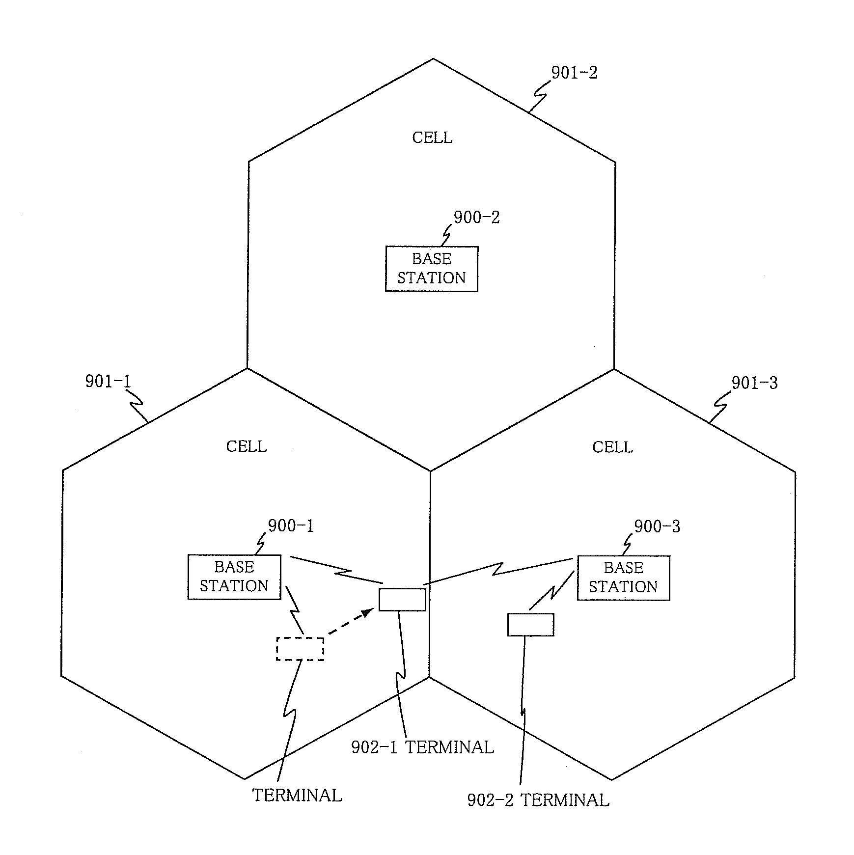
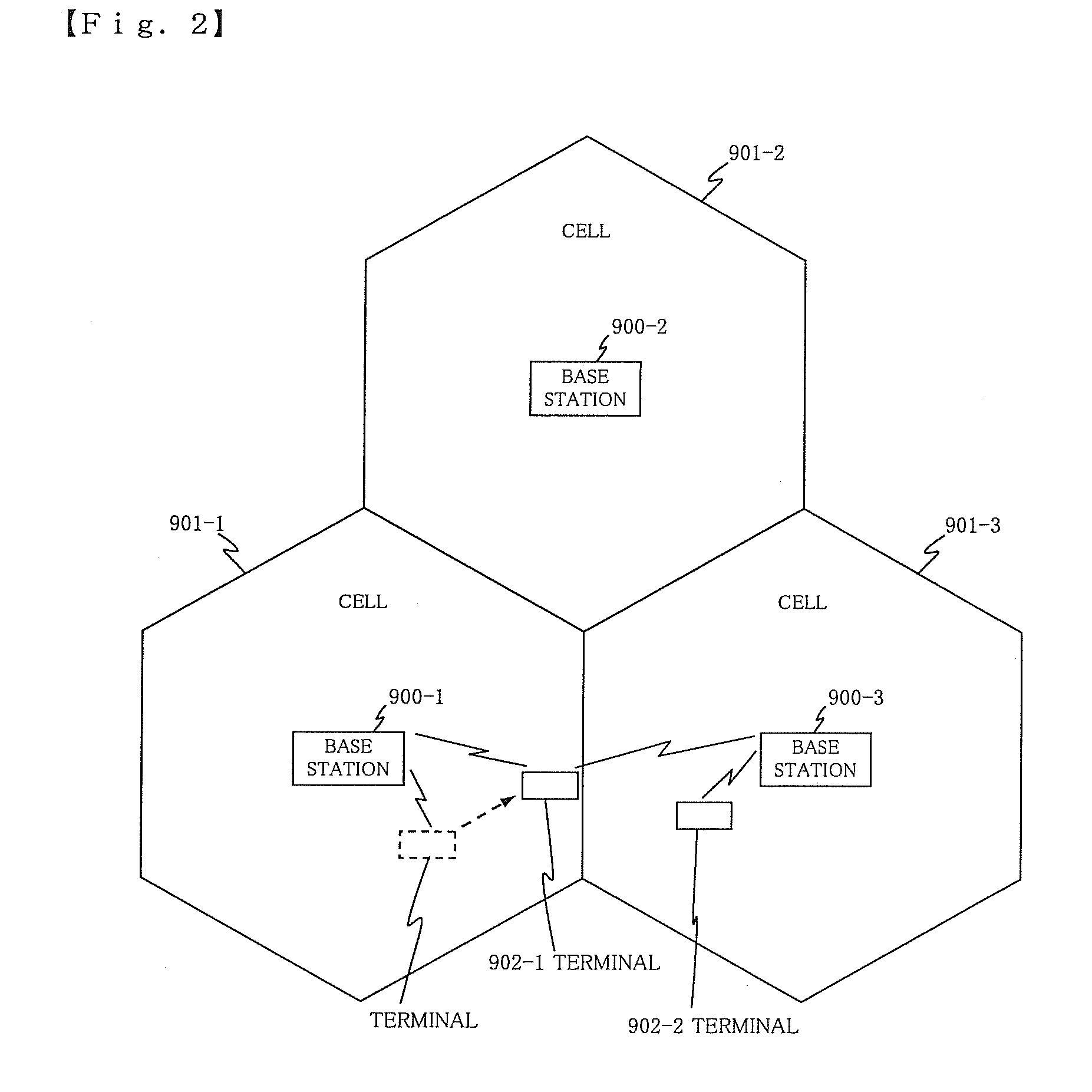
[0062]As shown in FIG. 4, the exemplary embodiment is composed of base stations 100-1 to 100-3 and terminals 102-1 to 102-2. Then, areas where communication is allowed between terminals 102-1 to 102-2 and base stations 100-1 to 100-3 are each defined in cells 101-1 to 101-3. Terminal 102-1 moves within cell 101-1 toward cell 101-3. Although the number of base stations 100-1 to 100-3 is three in this configuration, as will be described, the number thereof is not limited to three for carrying out the present invention. Although the number of terminals 102-1 to 102-2 is two in this configuration, as will be described, the number thereof is not limited to two for carrying out the present invention.

[0063]FIG. 5 is one configuration example of base station ...


PUM


Abstract

Base stations (100-1 to 100-3) communicate with terminals (102-1 to 102-2), divides a used frequency into a plurality of frequency blocks, and assigns the divided frequency block to terminal (102-1 to 102-2), in which a position at which terminal (102-1 to 102-2) exists is determined, and if it is determined that terminal (102-1 to 102-2) exists at the edge of cell (101-1 to 101-3), the assigned frequency block is set as a cell edge frequency block that is to be dynamically assigned at the edge of cell (101-1 to 101-3). In addition, if the cell edge frequency block has already been assigned to another terminal, this cell edge frequency block is assigned to terminal (102-1 to 102-2).

Description

TECHNICAL FIELD[0001]The present invention relates to a mobile communication system, a base station, and an inter-cell interference reduction method for reducing interference of radio waves between adjacent cells.BACKGROUND ART[0002]Conventionally, in a cell that is an area covered by a base station, the same broad frequency band is used with respect to one cell, and the frequency band is divided into some number of frequency blocks in the cell. Then, using the divided frequency block, communication is performed between a terminal and the base station existing in the cell. When assigning of the frequency blocks to the terminal, a propagation condition is measured by the base station based on a pilot signal sent from the terminal, and a frequency block whose propagation condition is good is assigned to the terminal, thus performing communication.[0003]In addition, to prevent overlapping of timings to send data from a plurality of terminals existing in the same frequency block each ot...

Claims


Application Information

Patent Timeline
Patent Type & Authority Applications(United States)
IPC IPC(8): H04B15/00H04W72/08
CPCH04W72/048H04W64/00H04W72/51H04W36/20
Inventor HASEBA, YUKIOIWASAKI, MOTOYAKAWABATA, HISASHINISHIMURA, OSAMIOKETANI, KENGOKONDOU, DAISUKE
Owner NEC CORP
Why Eureka
Try Eureka