Endoscopic attachment, endoscopic treatment instrument, and endoscope system

a technology for endoscopes and endoscopes, which is applied in the field of endoscope attachments, endoscope treatment instruments, and endoscope systems, can solve problems such as damage to the inner surface of the channel, and achieve the effect of restricting the rotation

Active Publication Date: 2009-02-12
OLYMPUS CORP
View PDF11 Cites 16 Cited by
  • Summary
  • Abstract
  • Description
  • Claims
  • Application Information

AI Technical Summary

Benefits of technology

[0009]An advantage of the invention is that it provides an endoscopic attachment, an endoscopic treatment instrument, and an endoscope system, which can selectively function only when an endoscopic treatment instrument of which a treatment portion needs to be restricted from being rotated is used, and can serve as a typical endoscope in other cases.
[0010]According to an aspect of the invention, an endoscopic attachment includes a cover portion that is mounted on a distal end of an inserted portion of an endoscope so as to cover a portion of an opening portion of a channel formed in the inserted portion of the endoscope; and an endoscope mounting portion that is fixed to the inserted portion of the endoscope. A non-circular deformed hole is formed in the opening portion of the channel by the cover portion, the rotation of an endoscopic treatment instrument, which projects from the opening of the channel and has a non-circular cross-section corresponding to the deformed hole, is restricted by the deformed hole, and the endoscopic treatment instrument freely moves in and out of the opening portion of the channel in a predetermined direction.
[0011]In accordance with this aspect, when the endoscopic treatment instrument provided with a flexible tube having a cross-section corresponding to the deformed hole formed by the cover potion is used and projected from the opening portion of the channel where the deformed hole is formed, the deformed hole of the cover portion restricts the flexible tube of the endoscopic treatment instrument from being rotated around the axis of the channel and projects the flexible tube in a predetermined direction.
[0012]According to another aspect of the invention, as a non-circular through-hole of which the area is set to be smaller than that of the opening of the channel is formed in the cover portion so as to communicate with the channel, the deformed hole is formed in the opening portion of the channel.
[0013]In accordance with this aspect, the flexible tube of the endoscopic treatment instrument is inserted into the non-circular through-hole, formed in the cover portion, from the channel so as to project. Then, the flexible tube of the endoscopic treatment instrument is restricted from being rotated around the axis of the channel and is projected in a predetermined direction.
[0014]According to a further aspect of the invention, an endoscope system includes the endoscopic attachment according to the first or second aspect; the endoscopic treatment instrument including a flexible tube having a non-circular cross-section, at least at the distal end thereof, corresponding to the shape of the deformed hole formed by the cover portion of the endoscopic attachment; and a treatment portion that freely moves in and out of the distal end of the flexible tube, is formed in a shape having an orientation around the axis of the flexible tube, and is restricted from being rotated; and the endoscope in which the channel into which the endoscopic treatment instrument can be inserted is provided in the inserted portion.

Problems solved by technology

Therefore, the inner surface of the channel may be damaged.

Method used


Image

  • Endoscopic attachment, endoscopic treatment instrument, and endoscope system
  • Endoscopic attachment, endoscopic treatment instrument, and endoscope system
  • Endoscopic attachment, endoscopic treatment instrument, and endoscope system

Examples


first embodiment

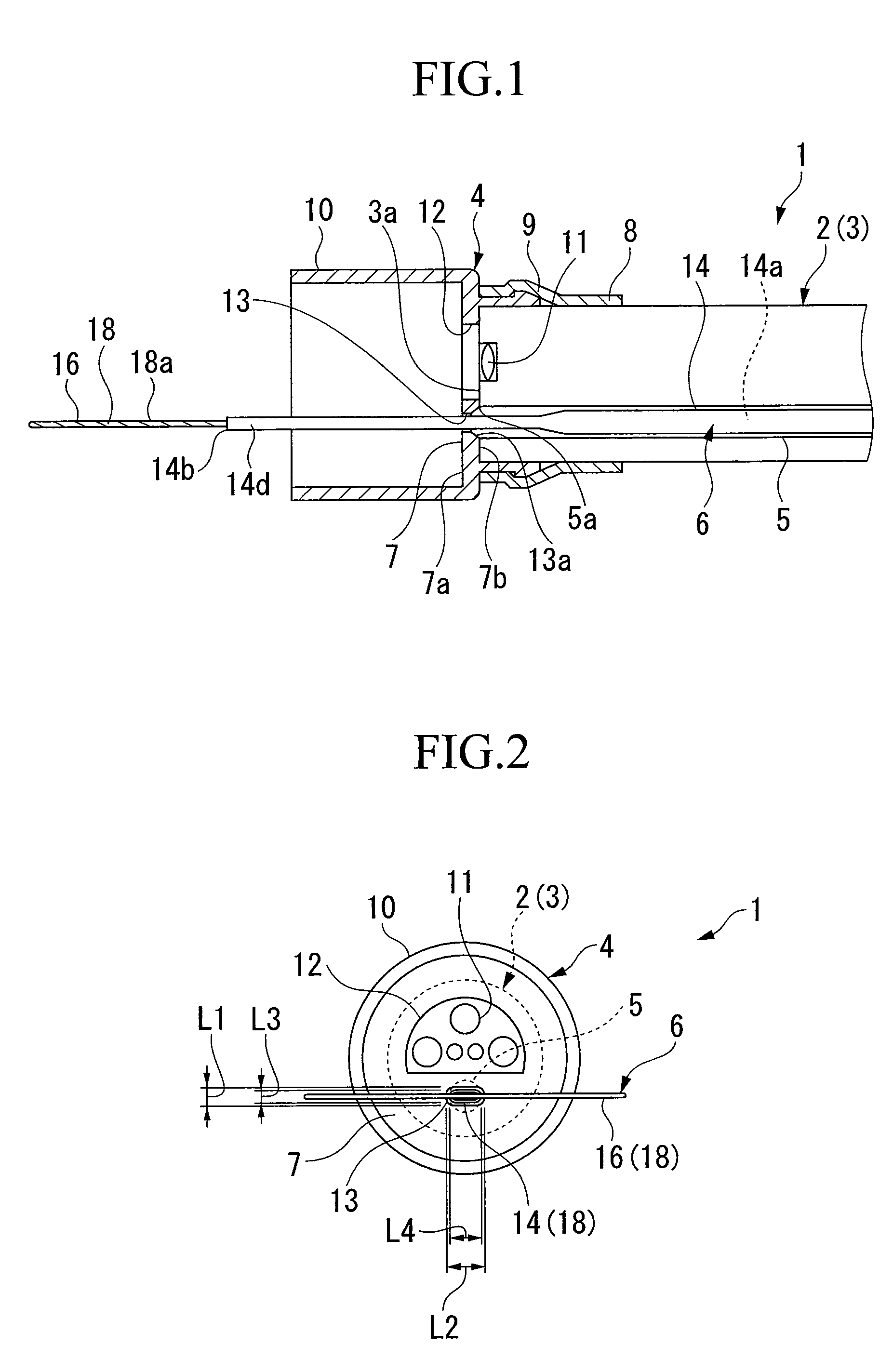
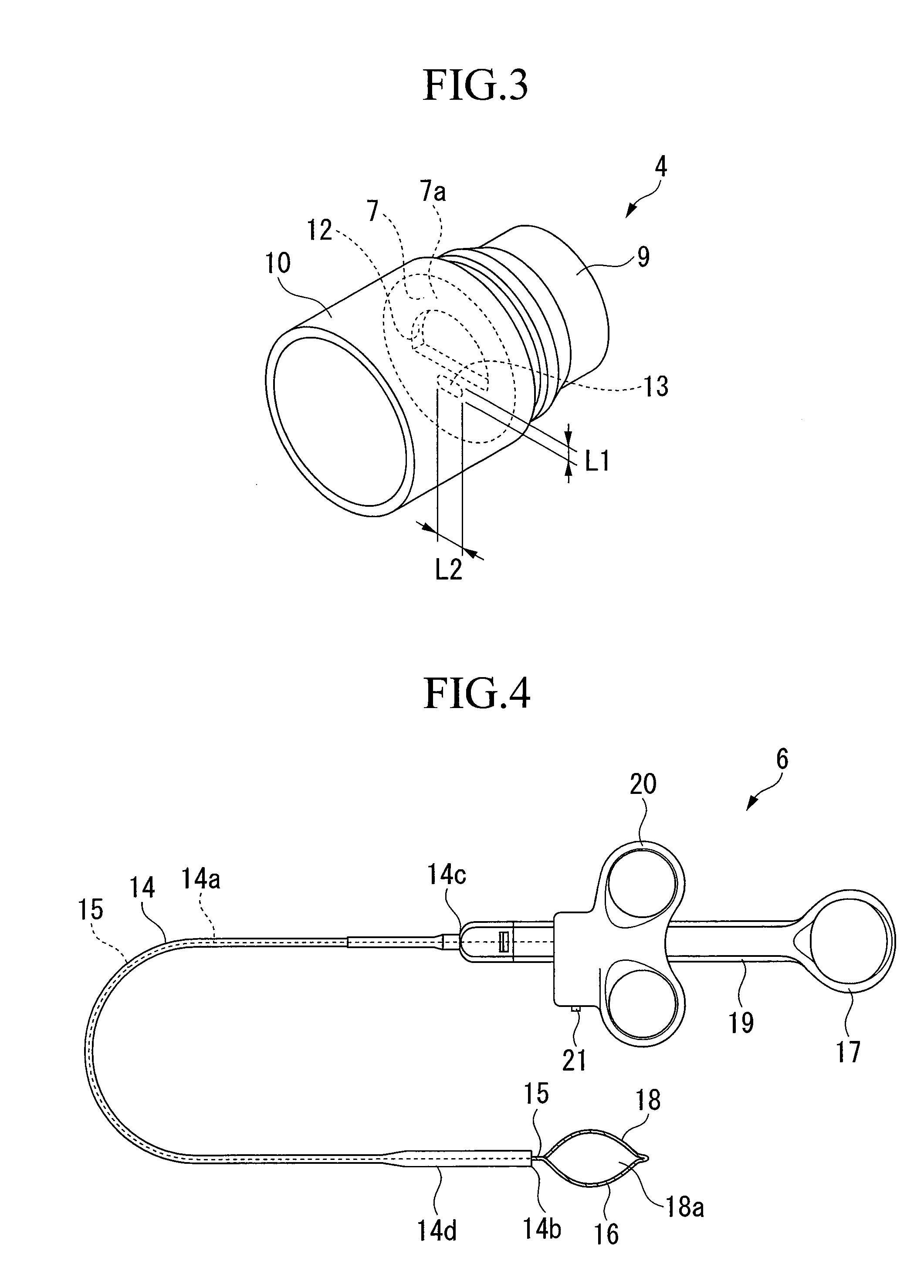
[0052]FIGS. 1 to 7 illustrate a first embodiment according to the present invention. FIG. 1 is a cross-sectional view of an endoscope system 1, and FIG. 2 is a front view of the endoscope system 1. FIG. 3 is a perspective view of an endoscopic attachment 4. FIG. 4 is an overall view of an endoscopic treatment instrument 6, and FIG. 5 is an expanded view of a distal end 14b of a flexible tube 14 of the endoscopic treatment instrument 6. FIGS. 6 and 7 are situation diagrams showing a state where the endoscope system 1 is used in a target portion.

[0053]As shown in FIG. 1, the endoscope system 1 includes an endoscope 2, an endoscopic attachment 4 mounted on a distal end 3a of an inserted portion 3 of the endoscope 2, and an endoscopic treatment instrument 6 which is inserted into a channel 5 from a base end (not shown) and freely moves in and out of an opening portion 5a of the channel 5 formed at the distal end 3a. The channel 5 passes through the inserted portion 3 of the endoscope 2 ...

second embodiment

[0064]FIG. 12 is a cross-sectional view of a second embodiment according to the invention. In this embodiment, like reference numerals are attached to the same components as those of the above-described embodiment, and the descriptions thereof will be omitted. In an endoscopic attachment 30 of this embodiment, the area of a deformed hole 31 passing through the cover portion 7 is set to be smaller than that of the opening portion 5a of the channel 5, and the deformed hole 31 is formed in a substantially elliptical shape which is elongated in the side-to-side direction rather than in the vertical direction. Further, guide members 32 are bonded to the inner surface 7b of the cover portion 7 above and under the opening portion of the deformed hole 3. When the endoscopic attachment 30 is mounted on the distal end 3a of the inserted portion 3 of the endoscope 2, the guide members 32 are abutted on the inner surface of the channel 5. One end 32a of each of the guide members 32 is bonded to...

third embodiment

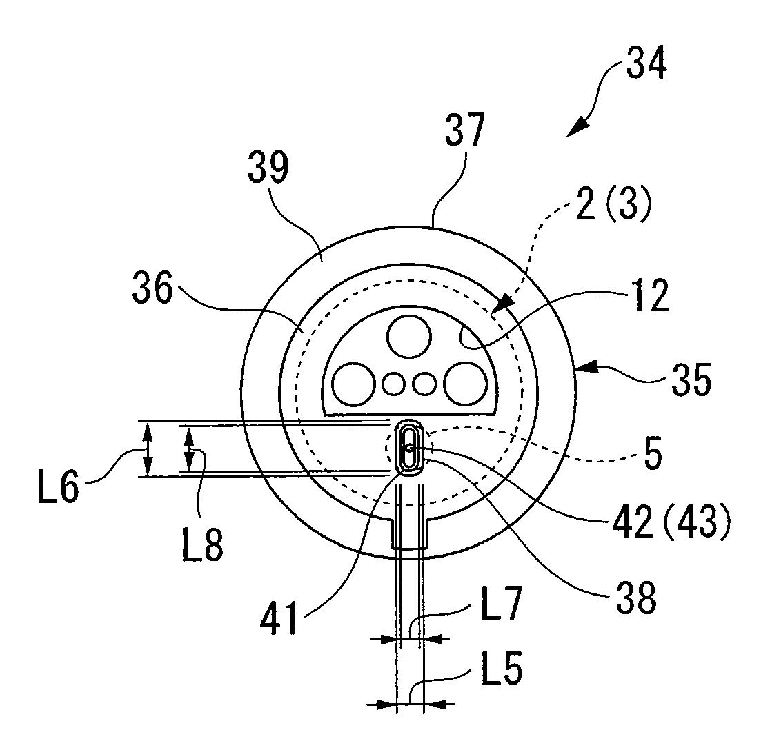
[0065]FIGS. 13 to 18 illustrate a third embodiment according to the invention. In this embodiment, like reference numerals are attached to the same components as those of the above-described embodiments, and the descriptions thereof will be omitted. FIG. 13 is a perspective view of an endoscope system 34 of this embodiment, and FIG. 14 is a front view of the endoscope system 34. FIG. 15 is a perspective view of an endoscopic attachment 35. FIG. 16 is an overall view of an endoscopic treatment instrument 40. FIG. 17 is an expanded view of a distal end 41 of a flexible tube 41 of the endoscopic treatment instrument 40. FIG. 18 is a condition diagram showing a state where the endoscope system 34 is used in a target portion.

[0066]As shown in FIGS. 13 to 15, the endoscopic attachment 35 of the endoscope system 34 of this embodiment includes a cover portion 36, a cap portion 37, and an endoscope mounting portion 9. The cover portion 36 has a deformed hole 38 passing therethrough. The area...


PUM


Abstract

An endoscope system has an endoscope; an attachment for the endoscope, having a non-circular irregularly shaped hole that communicates with an opening of a channel of the endoscope and attached to a forward end of an insertion section of the endoscope; and a treatment instrument for the endoscope, having a flexible tube and a treatment section. An extension/retraction section having a non-circular cross section corresponding to the shape of an opening of the irregularly shaped holes is provided at a forward end of the flexible tube, and the irregularly shaped hole restricts rotation of the flexible tube. Further, the treatment section has directivity about its axis relative to the flexible tube and its rotation is restricted.

Description

TECHNICAL FIELD[0001]The present invention relates to an endoscopic attachment mounted on a distal end of an inserted portion of an endoscope, an endoscopic treatment instrument assembled into the endoscope, and an endoscope system composed of the endoscopic attachment, the endoscopic treatment instrument, and the endoscope.[0002]Priority is claimed on Japanese Patent Application No. 2005-116943, filed Apr. 14, 2005, the content of which is incorporated herein by reference.BACKGROUND ART[0003]It is known that an endoscopic treatment instrument is inserted into a channel of an endoscope inserted into a body such that various treatments are performed on a target portion within the body by a treatment portion formed on a distal end of the endoscopic treatment instrument which projects from a distal end of an inserted portion of the endoscope. It is known that the treatment portion is formed in various shapes depending on treatments performed on a target portion. For example, there are ...

Claims


Application Information

Patent Timeline
Patent Type & Authority Applications(United States)
IPC IPC(8): A61B1/018
CPCA61B1/0008A61B1/00089A61B1/00101A61B1/018A61B2018/1407A61B2017/00269A61B2017/00296A61B2017/293A61B17/32056
Inventor OKADA, TSUTOMU
Owner OLYMPUS CORP
Why Eureka
Try Eureka