Endoscopic treatment tool

a technology of endoscopic treatment and treatment tool, which is applied in the field of endoscopic treatment tool, can solve the problems of rendering procedures more complicated and inconvenient to conduct adequate treatment, and achieve the effect of lowering compressive resistance and increasing rotation follow-up capability

Active Publication Date: 2011-03-24
OLYMPUS CORP
View PDF12 Cites 11 Cited by
  • Summary
  • Abstract
  • Description
  • Claims
  • Application Information

AI Technical Summary

Benefits of technology

[0009]An endoscopic treatment tool according to an aspect of the invention includes: a treatment part which is adapted to conduct treatment of tissue within a body cavity; an operation part which is adapted to operate the treatment part; an operation shaft member which connects the treatment part and the operation part; and a coil sheath part through which the operation shaft member passes so that the operation shaft member is capable of forward or backward movement, in which: the coil sheath part includes: a first coil sheath around which wire is helically wound; and a second coil sheath that has a lower

Problems solved by technology

Consequently, the coil sheath compresses in the axial direction, and the axial force to be transmitted to the distal

Method used


Image

  • Endoscopic treatment tool
  • Endoscopic treatment tool
  • Endoscopic treatment tool

Examples


first embodiment

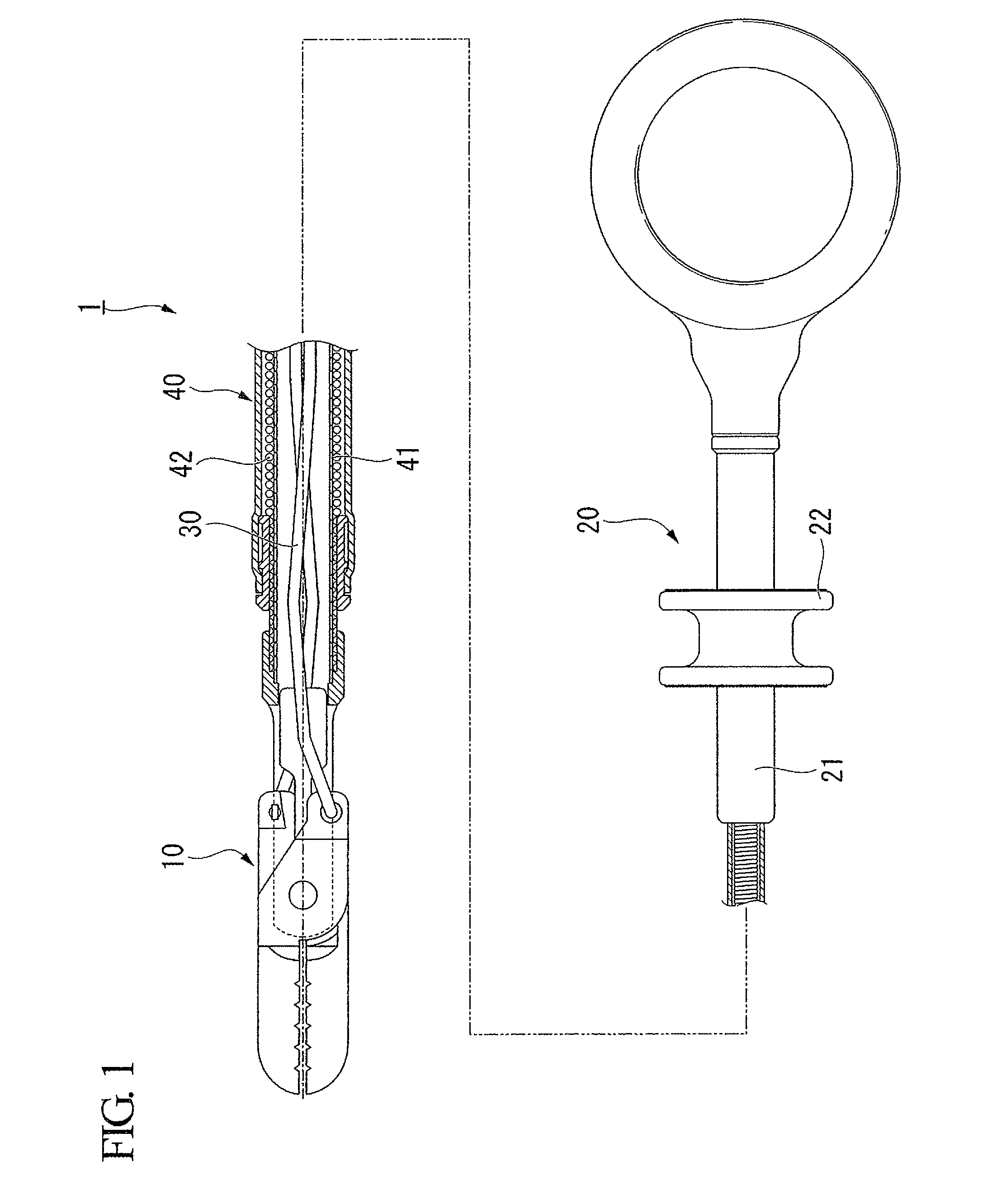
[0022]Below, an endoscopic treatment tool of the present invention is described with reference to FIG. 1 to FIG. 6. As shown in FIG. 1, an endoscopic treatment tool (hereinafter simply “treatment tool”) 1 of the present embodiment is provided with a treatment part 10 for conducting treatment of tissue within a body cavity, an operation part 20 for operating the treatment part 10, two operating wires (operation shaft members) 30 which connects the treatment part 10 and the operation part 20, and a coil sheath part 40 through which the operating wires 30 pass so as to be capable of forward and backward movement.

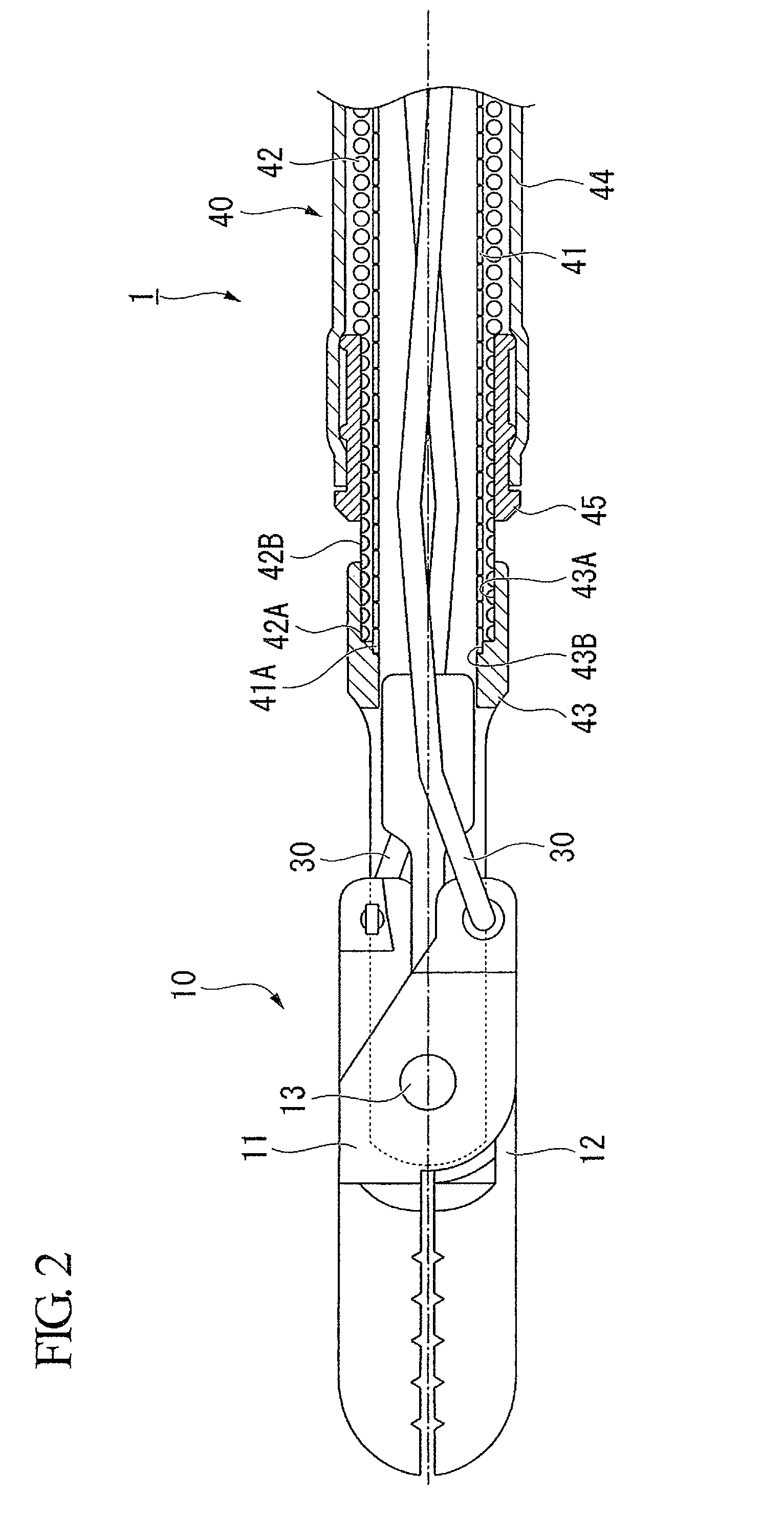
[0023]FIG. 2 is an enlarged sectional view of the distal portion of the treatment tool 1 including the treatment part 10. The treatment part 10 is configured by connecting a pair of forcep members—a first forcep member 11 and a second forcep member 12—with a pivot shaft 13 so as to be capable of mutually and freely turning. The operating wires 30 are connected to the proximal e...

second embodiment

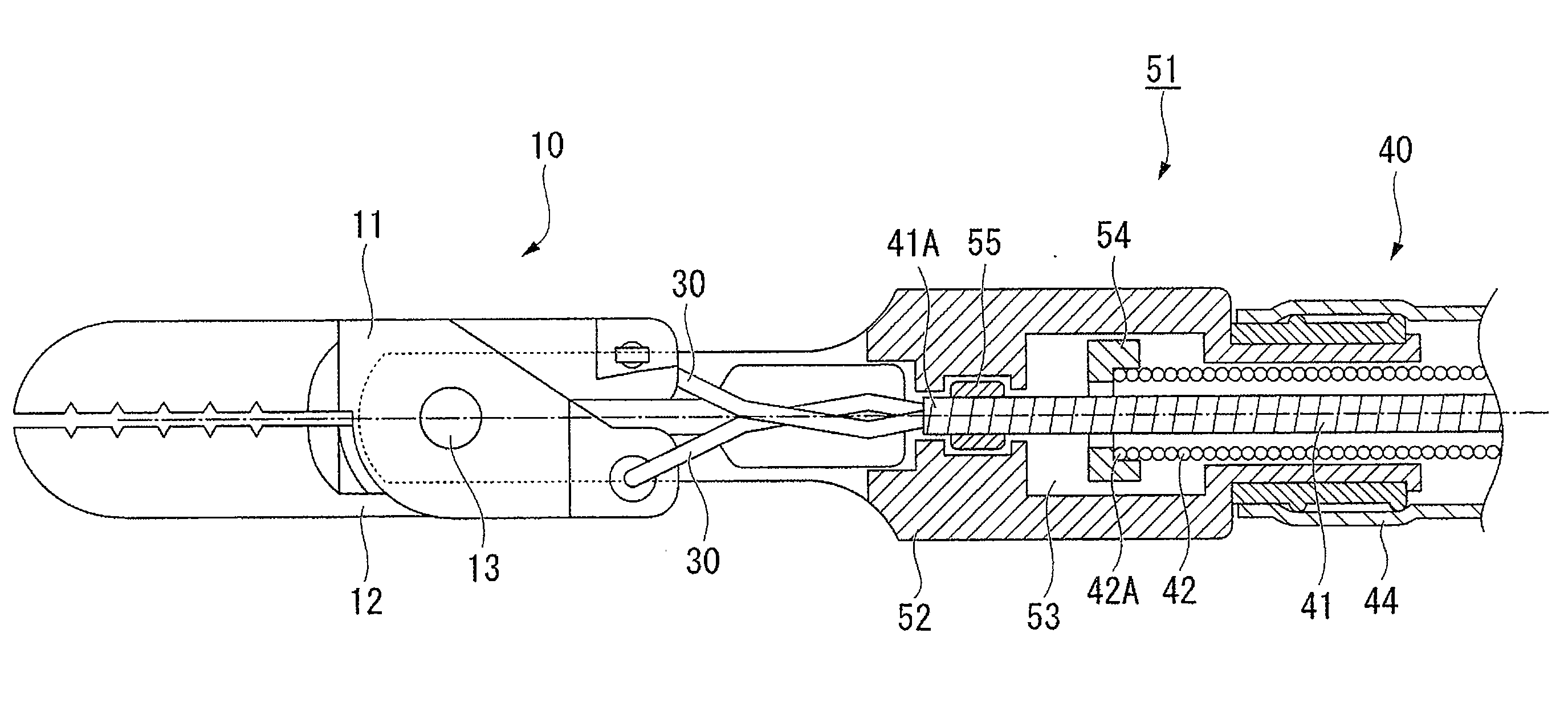
[0052]Next, the present invention is described with reference to FIG. 8. The difference between a treatment tool 51 of the present embodiment and the treatment tool 1 is the mode of connection of the coil sheath part to the treatment part and the operation part.

[0053]It should be noted that elements of configuration that are common to the treatment tool 1 of the first embodiment are given the same reference numerals, and duplicative description thereof is omitted.

[0054]FIG. 8 is an enlarged sectional view of the vicinity of the distal end of the coil sheath part 40 of the treatment tool 51. In the treatment tool 51, the treatment part 10 and the coil sheath 40 are connected by a connecting member 52.

[0055]The connecting member 52 has longer axial dimensions than the connecting member 43 of the first embodiment, and is attached so as to be capable of relative rotation around its own axis with respect to the tube 44.

[0056]A slide groove 53 having the same configuration as the slide gr...


PUM


Abstract

An endoscopic treatment tool includes: a treatment part which is adapted to conduct treatment of tissue within a body cavity; an operation part which is adapted to operate the treatment part; an operation shaft member which connects the treatment part and the operation part; and a coil sheath part through which the operation shaft member passes so that the operation shaft member is capable of forward or backward movement, in which: the coil sheath part comprises: a first coil sheath around which wire is helically wound; and a second coil sheath that has a lower compressive resistance than the first coil sheath, and that has a higher rotation follow-up capability than the first coil sheath; the first coil sheath and the second coil sheath are disposed so as to coaxially and radially overlap; a first end part and a second end part of the second coil sheath are respectively connected to the treatment part and the operation part so as to be incapable of relative rotation around an axis of the second coil sheath; and at least one of the first end part and the second end part is capable of relative movement in an axial direction with respect to the first coil sheath.

Description

BACKGROUND OF THE INVENTION[0001]1. Field of the Invention[0002]The present invention relates to an endoscopic treatment tool which is transendoscopically inserted into a body cavity and is employed in various procedures.[0003]Priority is claimed on Japanese Patent Application No. 2009-066248, filed Mar. 18, 2009, the content of which is incorporated herein by reference.[0004]2. Description of Related Art[0005]Conventionally, endoscopic treatment tools provided with a treatment part such as forceps at the distal end have been known. When conducting treatment on tissue within a body cavity using such an endoscopic treatment tool, it may be necessary to adjust the orientation of a treatment part when the orientation of the treatment part that projects into the body cavity is inappropriate relative to the position of the tissue as a treatment target. When such adjustments are conducted, it is important to cause the treatment part to rotate in precise response to the operations of an op...

Claims


Application Information

Patent Timeline
IPC IPC(8): A61B17/28
CPCA61B17/29A61B2017/2905A61B2017/2902
Inventor SUZUKI, KEITA
Owner OLYMPUS CORP
Why Eureka
Try Eureka