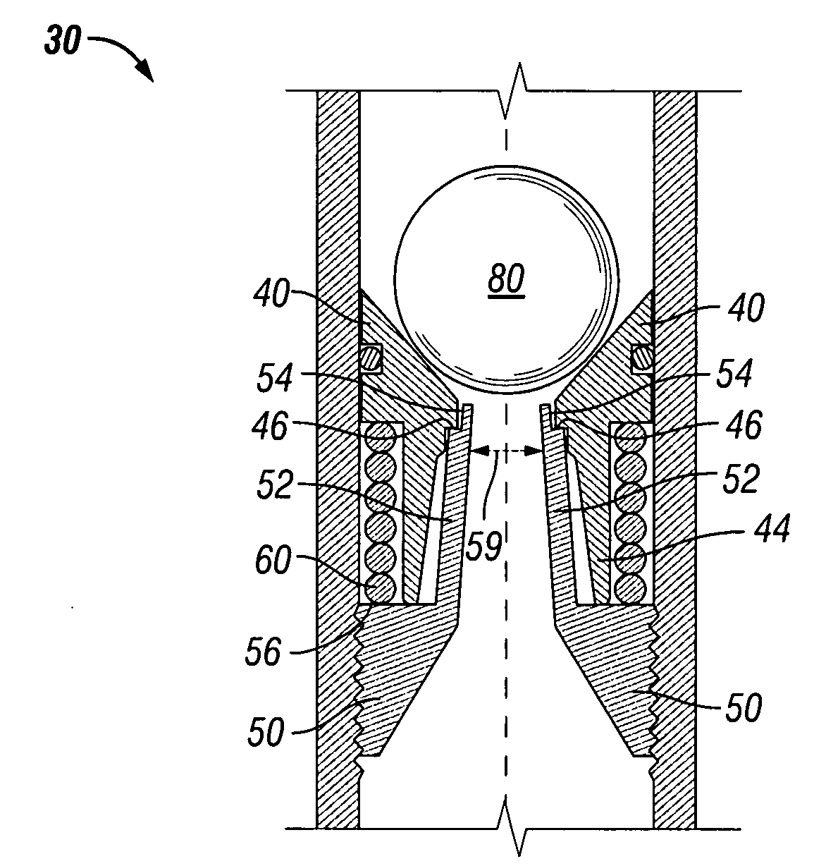
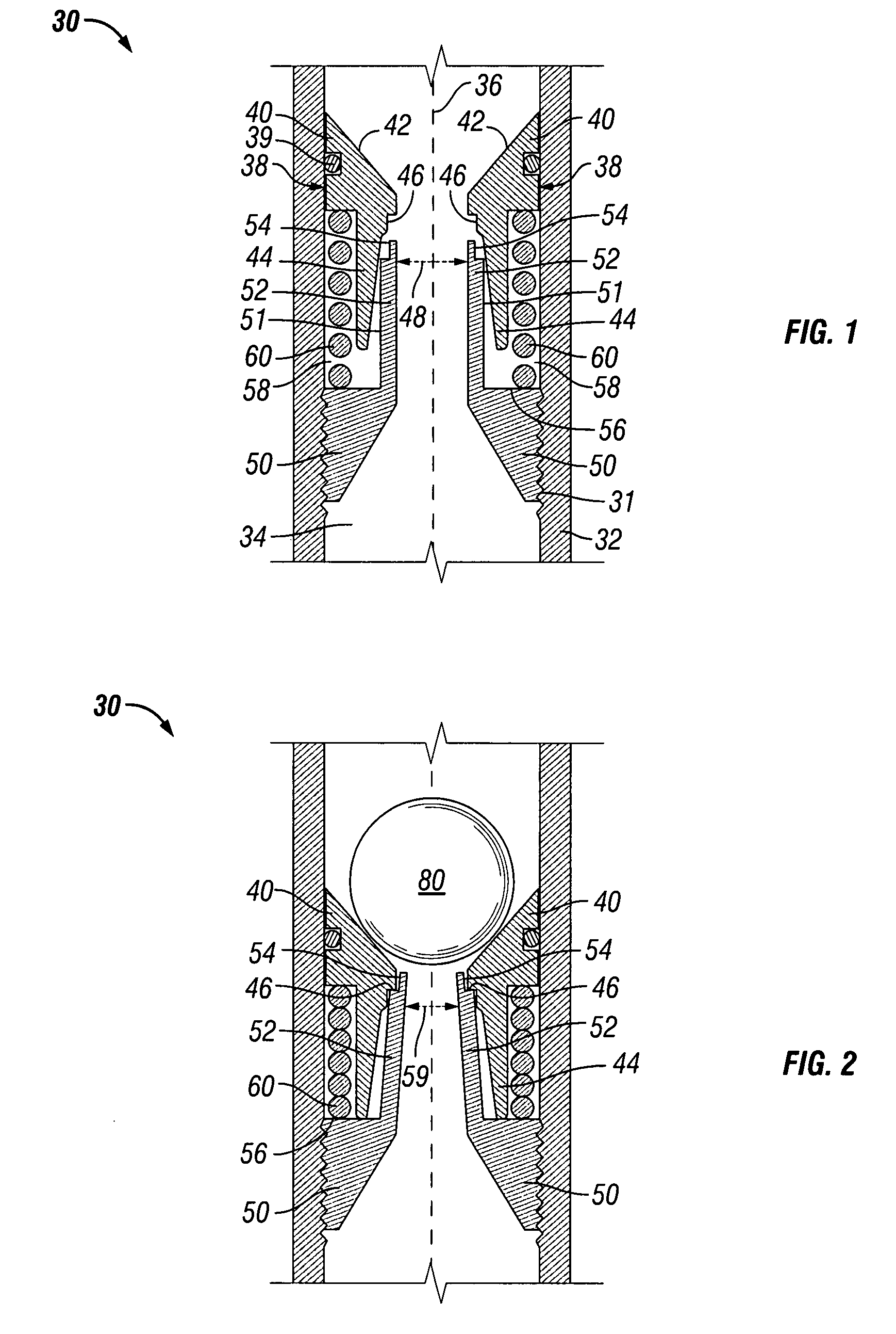
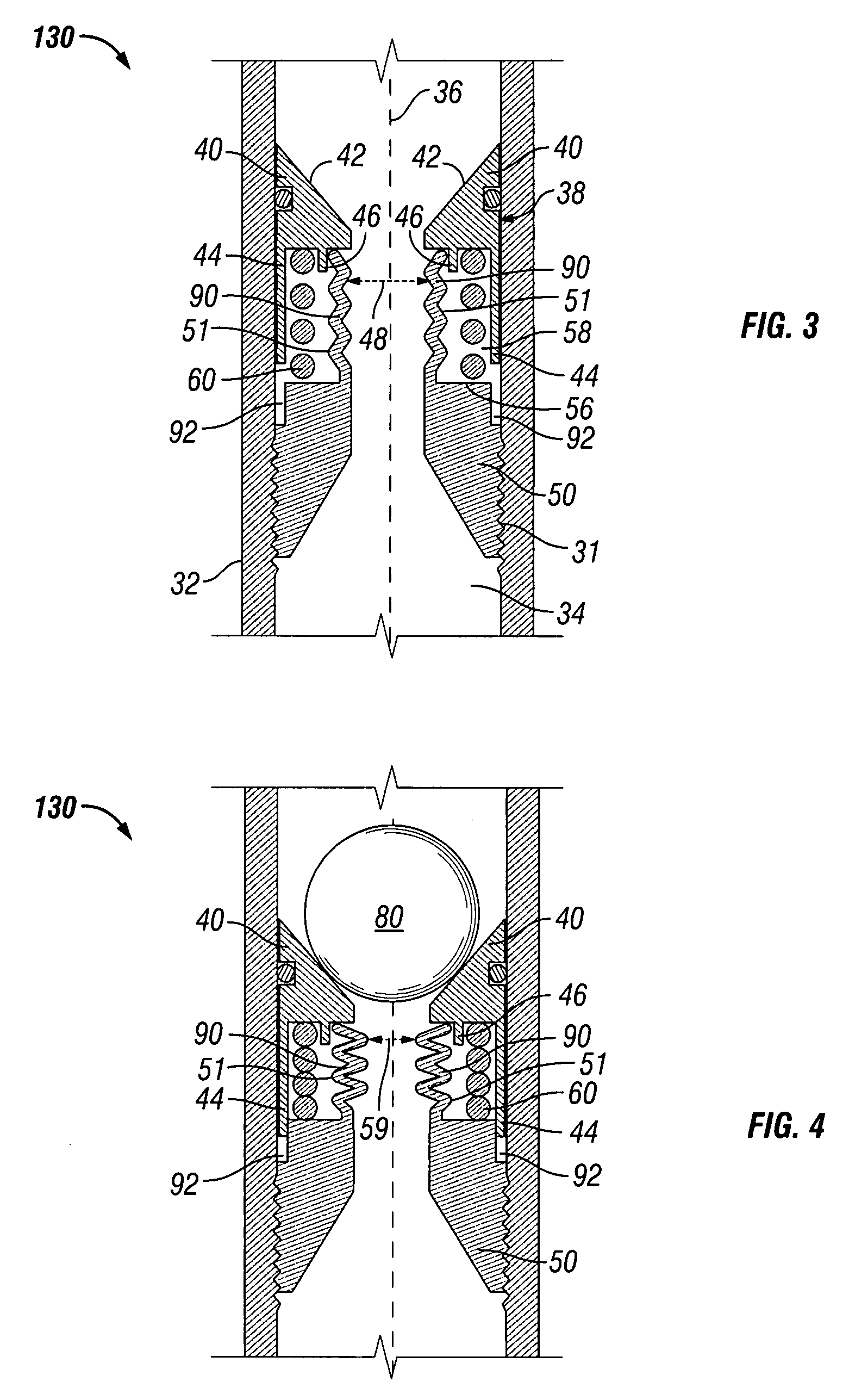
[0009]Broadly, ball seats having a housing, a seat, a ball support member, and a plug element such as a ball are disclosed. Typically, the ball is landed and the conduit is pressurized to a predetermined pressure. Upon pressurization of the conduit so that the ball is pushed into the seat, the seat forces a plug element support member to extend laterally, e.g., inwardly from its retracted position into the seat bore to reduce the seat inner
diameter as the ball seat bore is being pressurized. In other words, the force of the ball into the seat by the pressure in the tubing causes the seat to move the plug element support member inward into the bore of the ball seat from its retracted position toward the centerline (or axis) of the bore of the ball seat and into its extended positions, thus either making contact with the previously unsupported area of the ball or otherwise distributing the force acting on the ball over a larger surface area so that the ball and seat can withstand higher pressures and / or
restrict movement of the ball through the seat inner
diameter as the pressure begins to deform and extrude the ball through the seat.
[0010]By being moved laterally, e.g., inwardly toward the axis of the ball seat bore, the plug element support member provides support for the ball because the resulting force against the ball caused by pressurization of the ball against the seat is spread out between the existing seat contact area and the additional force distribution area provided by the extended plug element support member. The applied pressure to the plug element support member, therefore, decreases the likelihood that the force on the ball will push the ball through the seat or that the seat will otherwise fail.
[0011]Due to the plug element support member providing additional support to the ball, the ball seats disclosed herein provide a plugging method where higher pressure can be exerted onto a seat by a lower strength ball without exceeding the ball's bearing or load strength. Further, the
contact pressure resulting from having additional force distribution area provided by the plug element support members can be effectively reduced without affecting the sealability of the ball. Thus, more sizes of balls in closer increments can be utilized in various applications such as in frac ball systems. Additionally, more balls can be used because the seat inner diameter of subsequent seats can be larger due to the seat inner diameter of the seats of each ball seat in the conduit being larger. This allows more balls to go through the conduit because the seat inner diameters are larger throughout the length of conduit. Because more balls or plug elements can travel through the frac ball systems, more producible zones can be isolated by a single frac ball
system.
[0012]Therefore, additional force distribution area is provided by the plug element support member that allows a greater pressure to be exerted onto the ball while keeping the original seat inner diameter the same or, alternatively, allows a larger seat inner diameter with the current pressures. The additional force distribution area also allows the
contact pressure resulting from the tubing pressure onto the ball to be distributed to the standard seat contact area between the seat and the ball and the new areas provided by the plug element support member and the ball.
[0013]Furthermore, the ball seats include one or more return member, such as a coiled spring, belleville spring (also known as belleville washers), a spiral spring, or an elastomeric material, that urges the ball seat against the ball, i.e., against the
fluid pressure forcing the ball into the seat. This return member can be upwardly biased so that after fluid pressurization above the ball has performed its intended function, e.g., actuation of a downhole tool, and the fluid pressurization is decreased, the return member facilitates movement of the ball seat from the set position to the run-in position. In so doing, the ball is released and allowed to be recovered, such as by floating to the surface of the well, and the bore of the ball seat is moved towards its original run-in diameter. Accordingly, the ball seat can be reused at a later date to
restrict flow through the well conduit.

