Battery fixing device

a technology for fixing devices and batteries, which is applied in the direction of cell components, electric/fluid circuits, vehicle components, etc., can solve the problems of over-complexity of holding devices utilizing the upper surface of batteries, inability to safeguard the retention of batteries in their support tray, and high labor intensity of workers, so as to achieve easy manipulation

Inactive Publication Date: 2009-02-19
A RAYMOND & CO
View PDF8 Cites 28 Cited by
  • Summary
  • Abstract
  • Description
  • Claims
  • Application Information

AI Technical Summary

Benefits of technology

[0020]Such a hold-down device is therefore easy to manipulate and ensures safeguarded locking of the position of the battery, since all the levers are simultaneously made to move toward the locking position.

Problems solved by technology

However, this type of device calls for the use of tools, especially for tightening the nuts, and the manipulation of the various parts is exacting.
However, all these examples of hold-down devices utilizing the upper surface of the battery have proven overly complex, since they are made up of several easy-to-lose parts and necessitate the use of tools for installing and removing the battery.
Furthermore, the retention of the battery in its support tray is not safeguarded.
However, tools still have to be used to install and remove the battery, and the hold-down device is made up of several parts that are hard to manipulate.
In addition, the production cost of such a device is still high.
However, this type of device also requires the use of a screwdriver-type tool, especially during the removal of the battery.
In addition, dust can come to foul the internal friction zones of the hold-down device.
This then creates difficulties in removing the battery.
Although this type of device avoids the use of tools, it does not ensure safeguarded retention of the battery 11 in the support tray 12 and does not make it possible to determine whether the lug of the battery is actually in place.
In addition, such a hold-down device does not permit positive locking of the battery in the support tray.

Method used


Image

  • Battery fixing device
  • Battery fixing device
  • Battery fixing device

Examples


Embodiment Construction

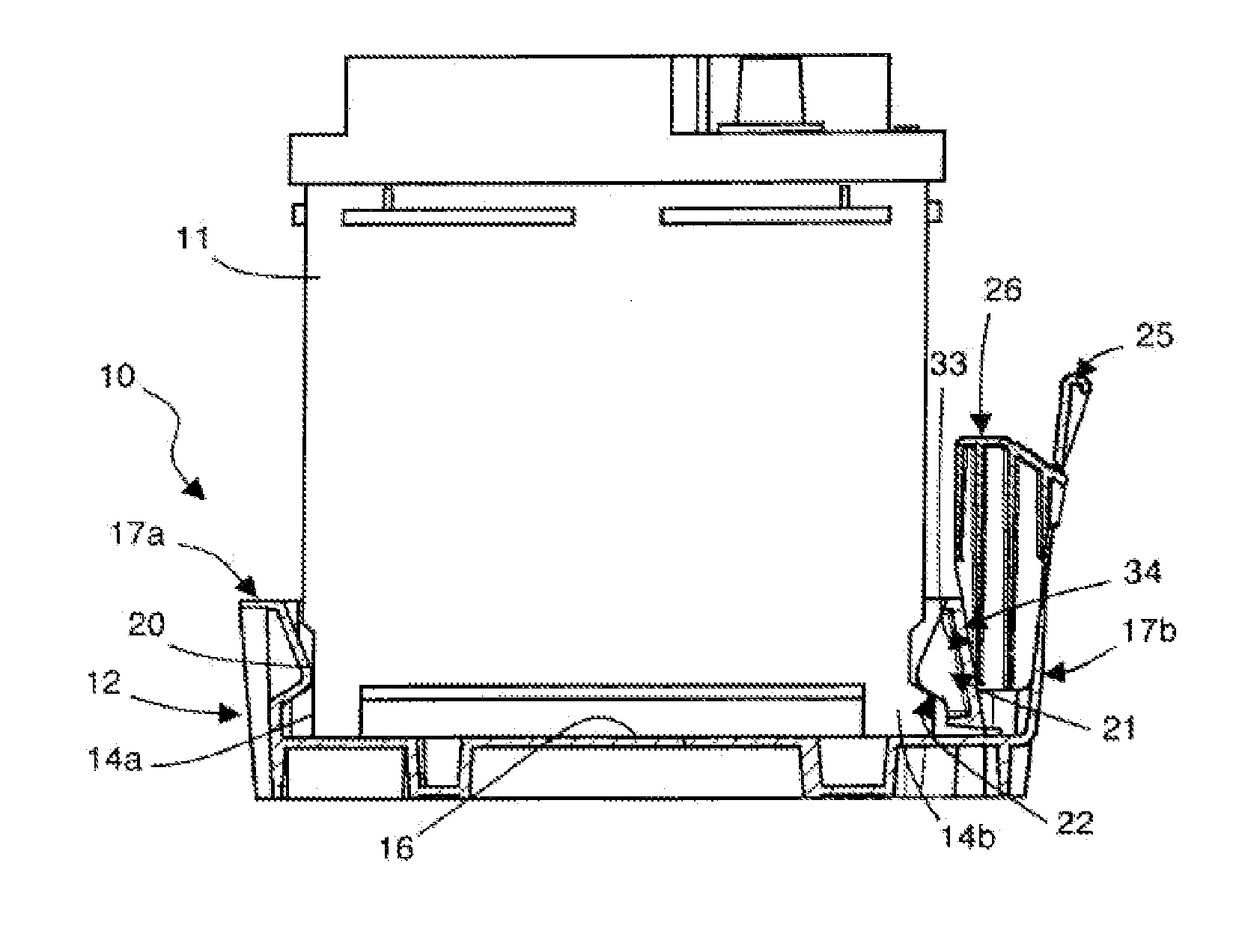
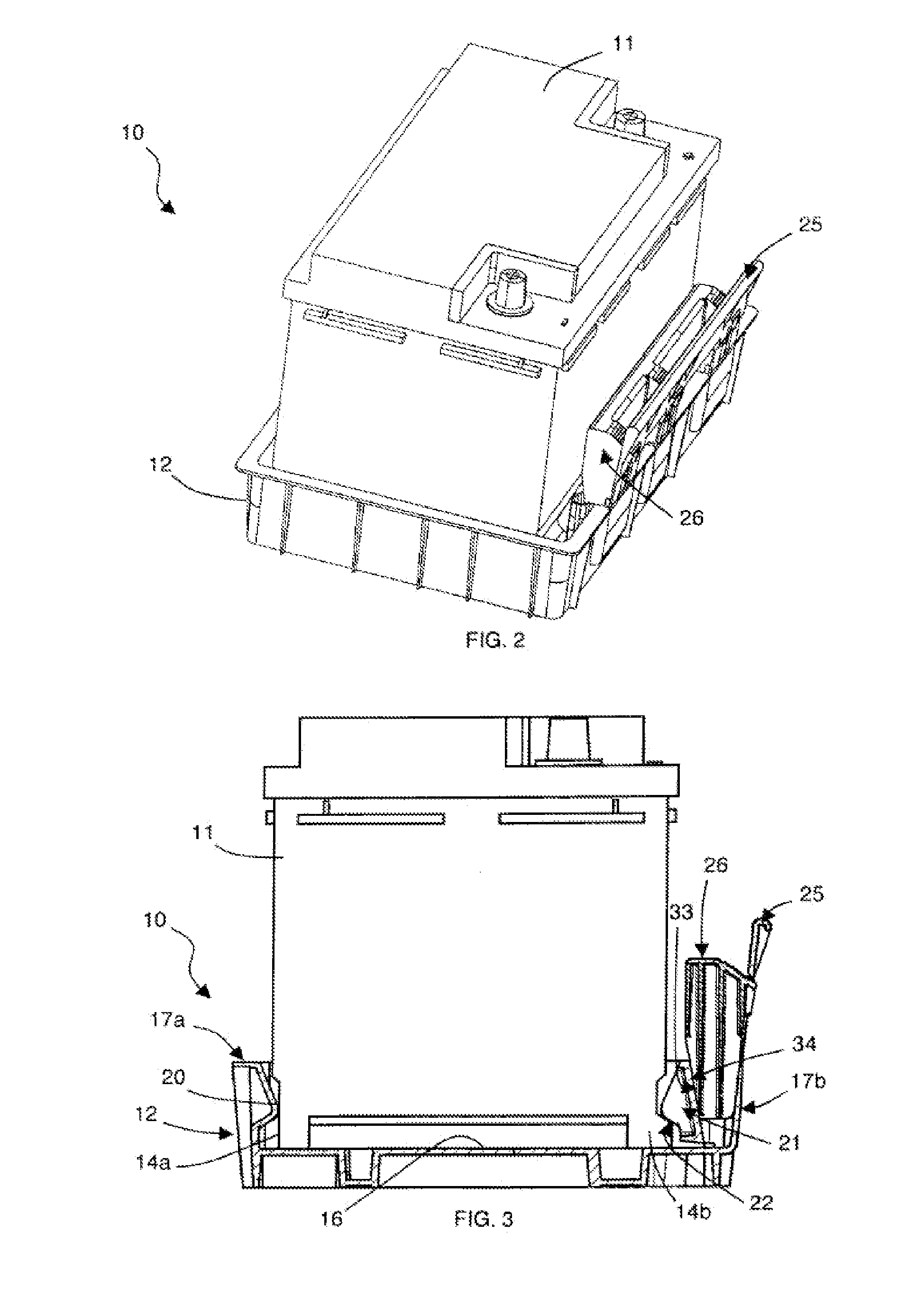
[0031]Referring to FIGS. 2 and 3, the hold-down device 10 is designed particularly to fix a battery 11 on the chassis of an automotive vehicle. Regardless of the standardized dimensions of the battery 11, the hold-down device 10 comprises a standard support tray 12 of substantially rectangular overall shape, capable of receiving all types of batteries, and a locking ramp 26 serving to lock the position of the battery 11 in its support tray 12.

[0032]The hold-down device 10 according to the invention therefore makes it possible, on the one hand, to immobilize the battery 11 in its support tray 12, and, on the other hand, to lock the position of the battery 11. The hold-down device 10 shifts from a first, locking position (FIGS. 2 and 3), in which the battery 11 is solidly fixed, to a second, unlocking position (FIGS. 11 to 14 and 18-19), in which the battery 11 can be removed.

[0033]In FIGS. 4 to 7, the support tray 12 of the battery 11 comprises a substantially planar resting surface ...


PUM

PropertyMeasurementUnit
flexibleaaaaaaaaaa
dimensionsaaaaaaaaaa
clamping pressureaaaaaaaaaa

Abstract

The invention relates to a device (10) for fixing a battery (11), consisting of a support tray (12) comprising an essentially-flat support face (16) and two longitudinal flanges (17a, 17b). According to the invention, the first longitudinal flange (17a) comprises fixed lugs (20) which serve as positioning stops for a first lug (14a) of the battery (11). The support tray (12) comprises mobile lugs (21) which are connected to the second longitudinal flange (17b) and which each define a first blocking surface (22) for a second lug (14b) of the battery (11). The fixing device (10) comprises elastically-deformable actuation levers (25) which are associated with the mobile lugs (21) and a locking ramp (26) which co-operates with each mobile lug (21) and each corresponding actuation lever (25) such as to lock the battery (11) in position in the support tray (12).

Description

BACKGROUND OF THE INVENTION[0001]1. Field of the Invention[0002]The present invention concerns a hold-down device for a battery, particularly for automotive vehicles.[0003]2. Description of the Related Art[0004]In all types of automotive vehicles, the battery is a standard component whose dimensions are governed by precise standards. There are various types of known hold-down devices for placing and immobilizing the battery on the chassis of the vehicle. A first type of known hold-down device utilizes the upper surface of the battery and a second type of known hold-down device utilizes the lugs of the battery.[0005]A first example of a hold-down device utilizing the upper surface of the battery consists in resting the battery on a support tray, placing two vertical rods one on each side of the battery and positioning a bracketing element that connects the two vertical rods above the battery. The hold-down device then exerts a vertical clamping action on the battery by bearing on its...

Claims


Application Information

Patent Timeline
Patent Type & Authority Applications(United States)
IPC IPC(8): B60R16/04H01M50/202H01M50/244
CPCH01M2/1083B60R16/04Y02E60/10H01M50/202H01M50/244
Inventor PICAVET, CHRISTOPHE
Owner A RAYMOND & CO
Why Eureka
Try Eureka