Bin tunnel with collapsible sides

Active Publication Date: 2009-02-19
SHRED TECH CORP
View PDF8 Cites 2 Cited by
  • Summary
  • Abstract
  • Description
  • Claims
  • Application Information

AI Technical Summary

Benefits of technology

[0008]It is an object of the present invention to provide a bin tunnel having collapsible sides so that a depth of the bin tunnel in a closed position is substantially less than fifty (50) percent of the depth of the bin tunnel in an open position.
[0009]A bin tunnel is used with a truck box of a truck to load the content into the truck using a bin that is sized to fit into the bin tunnel. The bin tunnel comprises an outer portion, being a front, a top and two sides and an inner portion with a lift mechanism mounted on an inner wall thereof, the inner wall being fixed within said truck box. The outer portion is slidably supported on the truck box to enable the outer portion to be moved outward from the truck box to an open position of the bin tunnel and moved inward to a closed position of the bin tunnel in which the front is substantially flush with an outer side wall of the truck box. The outer portion of the bin tunnel is supported on the truck box independently of the sides, the sides being collapsible relative to the front. In the open position, the bin tunnel has sufficient height, depth and width to receive the bin, the lift mechanism being constructed to removably connect to the bin and to raise the bin upward within the bin tunnel and tilt the bin to empty the contents of the bin into the truck box. A depth of the bin tunnel in the closed position being substantially less than fifty (50) percent of the depth of the bin tunnel in the open position, the sides being extended in the open position and retracted in the closed position.
[0010]A bin tunnel is used with a truck box of a

Problems solved by technology

Since the usable width of the truck box is reduced by the inner wall, this reduces the size of the payload of the truck and decreases the efficiency of the truck.
Also, for mobile document systems where content is collected by a truck for shredding at another location, since the bin tunnel narrows the inner width of the truck box by the same distance that the bin tunnel extends beyond the sidewall of the truck box when the bin tunnel is in the open position, a standard size fork lift will not fit into the truck box for unloading.
This access can be a security problem when the contents of the truck box are not shredded.

Method used


Image

  • Bin tunnel with collapsible sides
  • Bin tunnel with collapsible sides
  • Bin tunnel with collapsible sides

Examples


Embodiment Construction

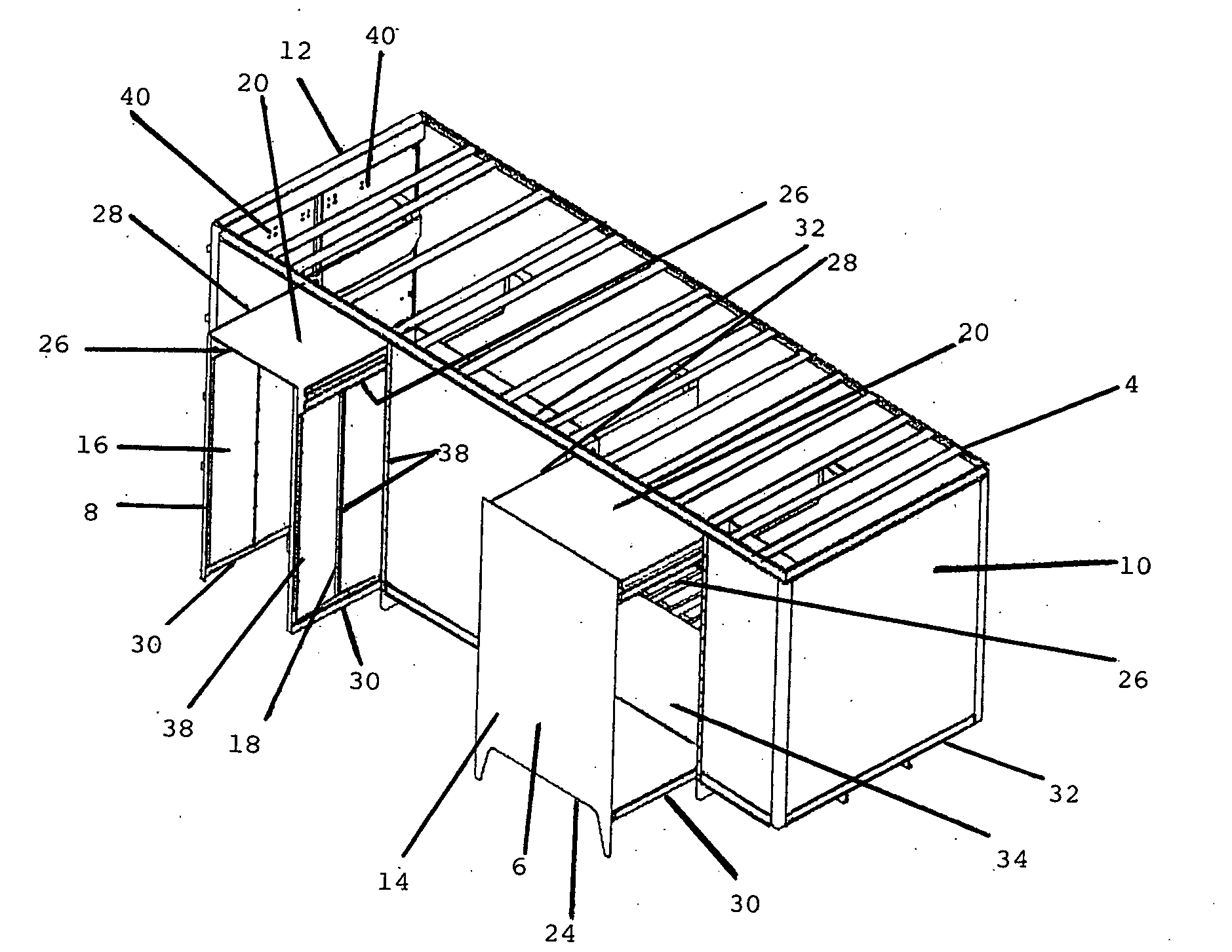
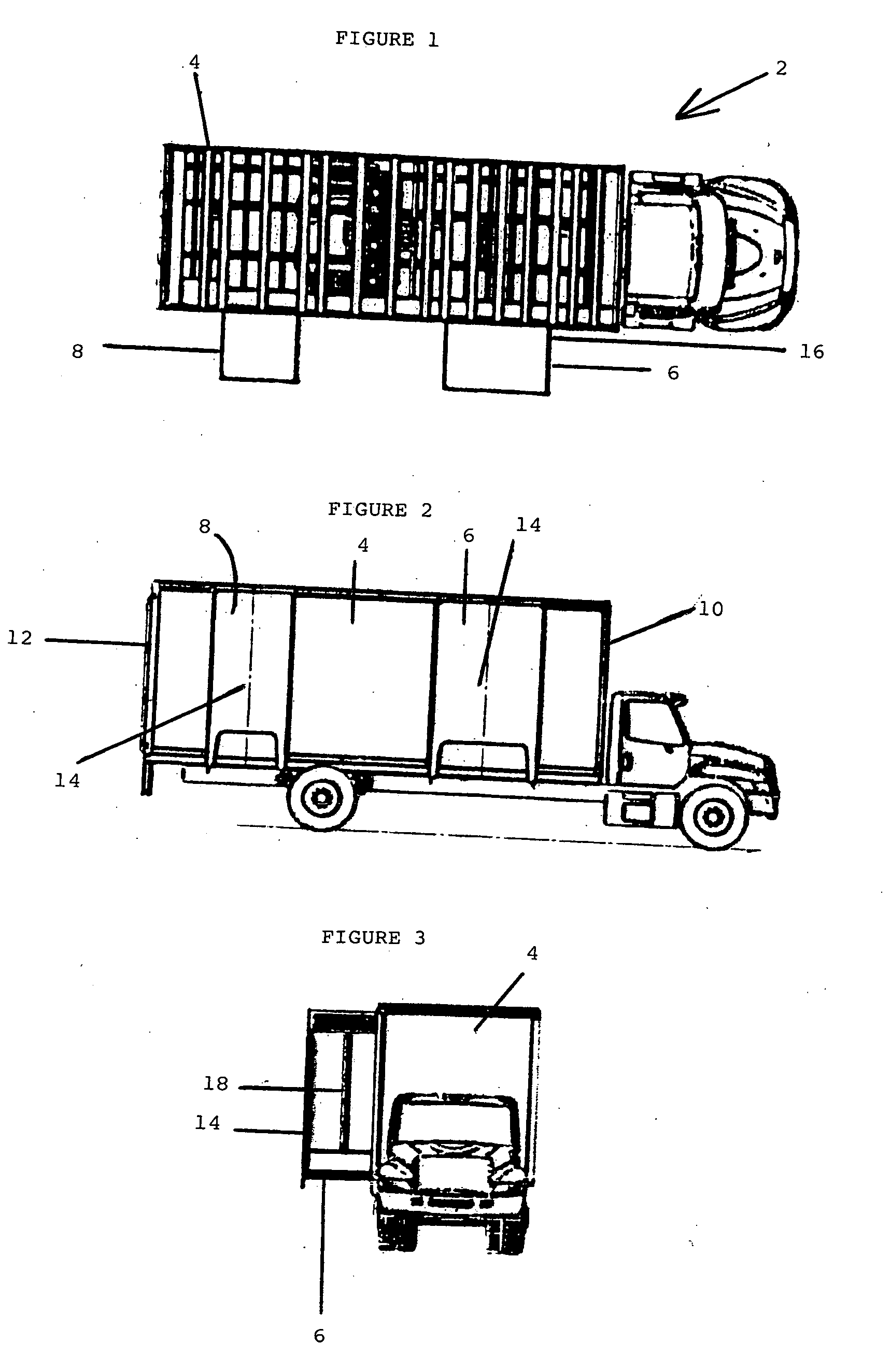
[0032]In FIGS. 1 to 3, a truck 2 has a truck box 4 with two schematically shown bin tunnels 6, 8 in an open position. The bin tunnels 6, 8 are located on a passenger side of the truck 2 and the bin tunnel 6 is located near a front 10 of the truck box 4 and the bin tunnel 8 is located near a rear 12 of the truck box 4. The bin tunnel 6 is larger than the bin tunnel 8 and each bin tunnel has an outer wall 14 and two sidewalls 16. The bin tunnel 6 can receive larger bins (not shown) than the bin tunnel 8. In FIG. 3, it can be seen that the sidewalls 16 (only one of which is shown) are collapsible as each sidewall has a fold line 18 therein. The roof and floor have been omitted from FIG. 1 to show the structural supports.

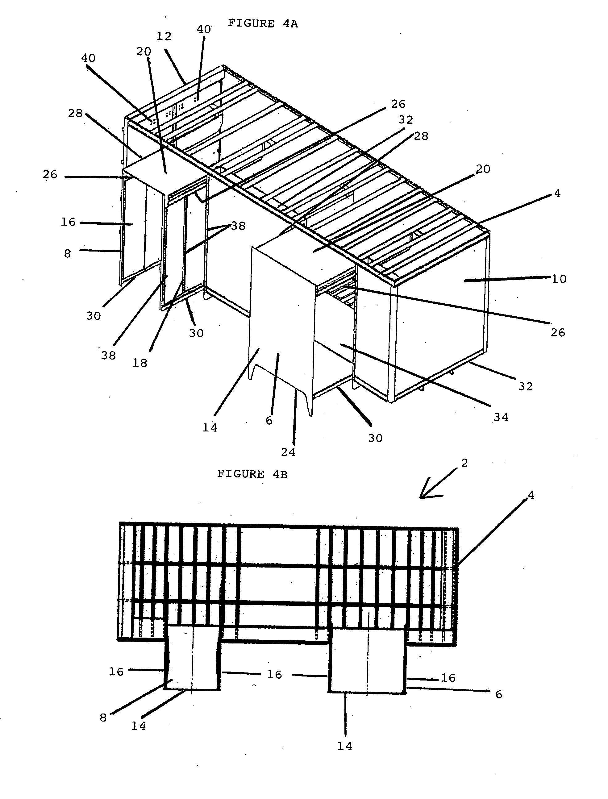
[0033]In FIG. 4, both bin tunnels 6, 8 are in the open position and each bin tunnel has a roof 20 thereon. The bin tunnel 6 has an outer wall or front 14 installed thereon but no sidewalls are installed. The outer wall 14 has an inverted U-shaped lower portion 24 to pro...


PUM


Abstract

A bin tunnel having collapsible sides is used with a truck box of a truck to load content into the truck box from a bin that is sized to fit within the bin tunnel when the bin tunnel is in an open position. When the bin tunnel is in a closed position a footprint of the bin tunnel is very small compared to the open position because the sides are retracted. The footprints can be less when the bin tunnel is in the closed position from thirty (30) percent of the footprint of the bin tunnel in the open position. When the bin tunnel is closed, the contents of the truck box are secure as the space inside of the closed bin tunnel is too small to allow access to the interior.

Description

[0001]Applicant claims the benefit of U.S. Provisional Application Ser. No. 60 / 956,280 filed on Aug. 16, 2007BACKGROUND OF THE INVENTION[0002]1. Field of the Invention[0003]This invention relates to a bin tunnel for use with a truck box of a truck to load content into the truck box using a bin that is sized to fit into the bin tunnel when the bin tunnel is in an open position, the bin tunnel having collapsible sides, resulting in a small footprint when the bin tunnel is in a closed position.[0004]2. Description of the Prior Art[0005]It is known to have bin tunnels to load the content of a bin into a truck box of a truck. Bin tunnels have a closed position in which an outer wall of the bin tunnel is flush with an outer wall of the truck box. When the truck is being driven, the bin tunnel is in the closed position. When the truck is stopped and it is desired to empty the contents of one or more bins into the truck box, the bin tunnel is pulled outward from the truck box to an open pos...

Claims


Application Information

Patent Timeline
IPC IPC(8): B60P3/40
CPCB65F2240/1562B65F3/00Y02W30/64
Inventor ROBERTO, JOSEPH F.YAMAMOTO, DAVID K.POLLOCK, IAN R.
Owner SHRED TECH CORP
Why Eureka
Try Eureka