System and method for testing a video signal generator

a video signal and generator technology, applied in the field of system and method for testing a video signal generator, can solve the problems of heavy and complicated test methods, slow test speed, and damage to video signal generator components or assemblies,

Inactive Publication Date: 2009-02-19
HONG FU JIN PRECISION IND (SHENZHEN) CO LTD +1
View PDF9 Cites 8 Cited by
  • Summary
  • Abstract
  • Description
  • Claims
  • Application Information

AI Technical Summary

Benefits of technology

[0008]A computer-enabled method for testing a video signal generator includes: setting test parameters of the video signal generator to perform a function test; generating signals based on the test parameters; controlling a standard measuring apparatus to receive the signals and to convert the signals into test values; determining whether the video signal generator passes the function test by comparing the test values with a standard working range of the video signal generators; and generating a test report based on the test values and the test parameters.

Problems solved by technology

For this reason, the test method is heavy and complicated, and the test speed is slow.
In addition, components or assemblies of the video signal generator would be damaged through repeatedly testing.
Test reports also need to be manually inputted, thus, the test reports may consist of typo errors.

Method used


Image

  • System and method for testing a video signal generator
  • System and method for testing a video signal generator
  • System and method for testing a video signal generator

Examples


Embodiment Construction

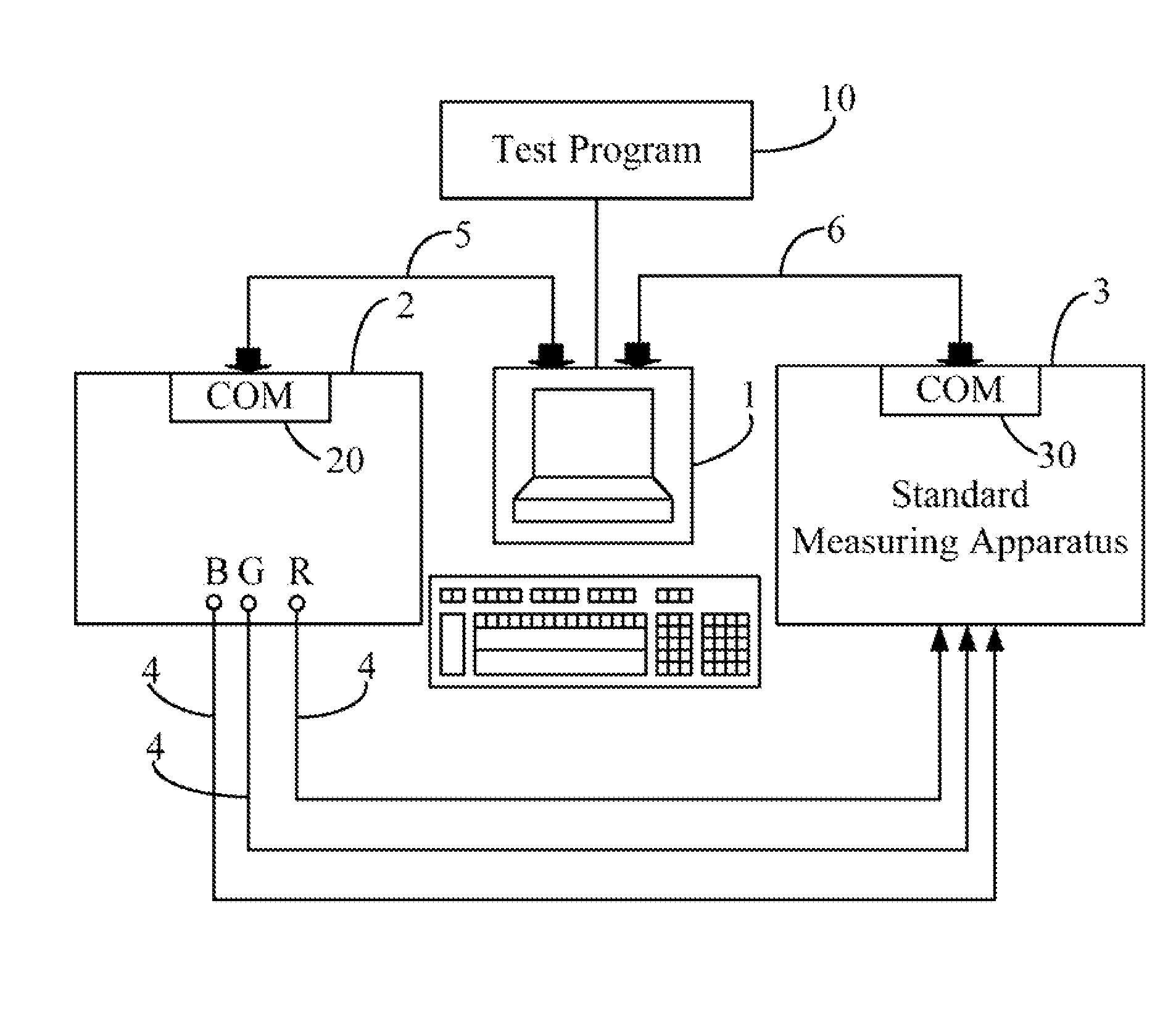
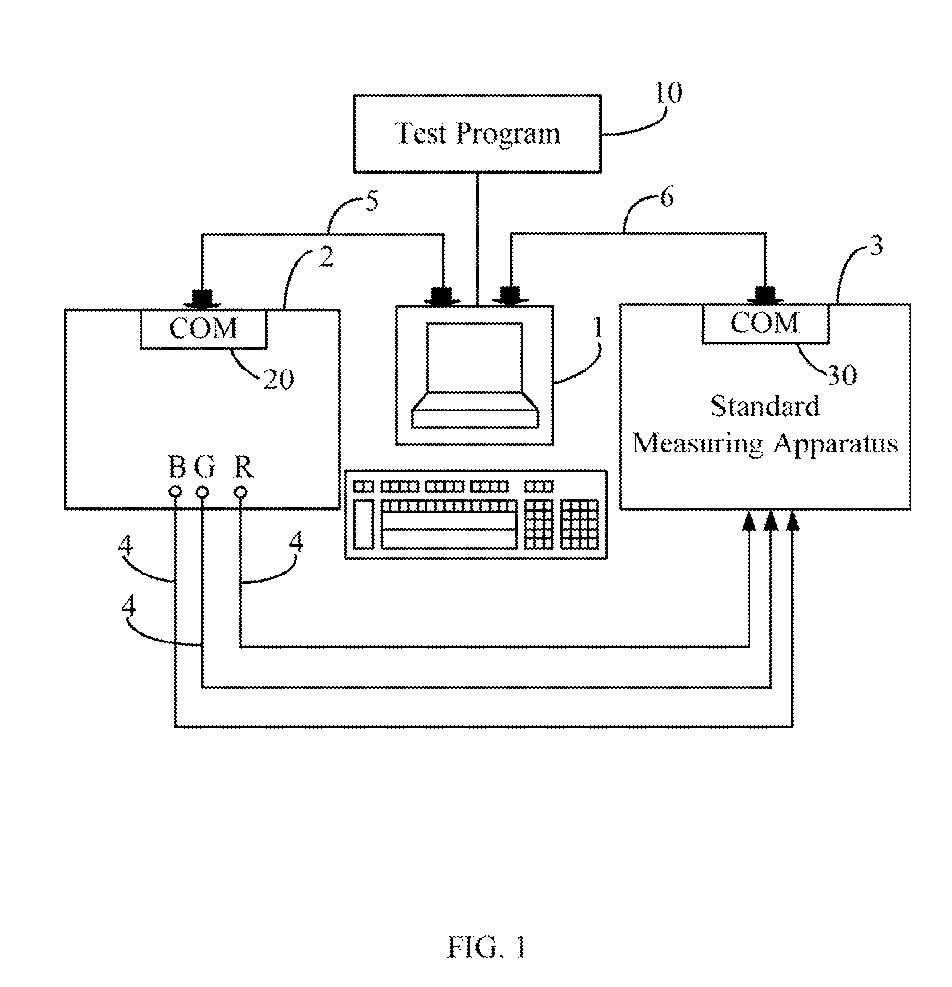
[0014]FIG. 1 is a schematic diagram illustrating an application environment of a system for testing a video signal generator (hereinafter, “the system”) in accordance with one embodiment. The system typically includes a computer 1, a video signal generator 2 and a standard measuring apparatus 3. The computer 1 includes two ports: a first COM port and a second COM port. The video signal generator 2 includes at least one COM port 20 that is connected with the first COM port of the computer 1 via a first data line 5. The standard measuring apparatus 3 includes, but not limited to, a COM port 30 that is connected with the second COM port of the computer 1 via a second data line 6. The video signal generator 2 is electronically linked with the standard measuring apparatus 3 via a plurality of conducting lines 4.

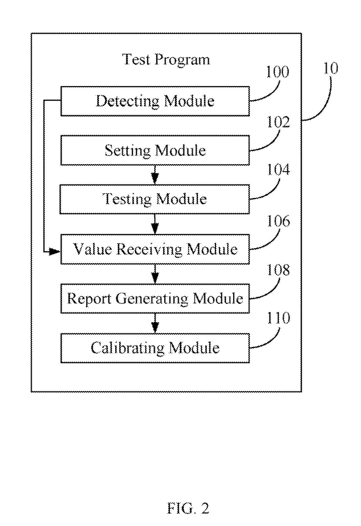
[0015]In the preferred embodiment, the computer 1 is installed with a test program 10, which can provide a graphical user interface on the computer 1 for setting test parameters. ...


PUM


Abstract

An exemplary method for testing a video signal generator is provided. The method includes: setting test parameters of the video signal generator to perform a function test; generating signals based on the test parameters through the video generator; controlling a standard measuring apparatus to receive the signals and to convert the signals into test values; determining whether the video signal generator passes the function test by comparing the test values with a standard working range of the video signal generators; and generating a test report based on the test values and the test parameters. A system for testing a video signal generator is also provided. By utilizing the present invention, errors can be reduced and test efficiency can be enhanced.

Description

BACKGROUND OF THE INVENTION[0001]1. Field of the Invention[0002]The present invention relates to systems and methods for testing signal generators, particularly to a system and method for testing a video signal generator.[0003]2. Description of Related Art[0004]For a video display to operate a high resolution with high fidelity of colors, the quality of a video signal generator is very important. For this reason, a function test needs to be performed on the video signal generator accurately and efficiently to check the quality of the generator after the video signal generator is produced.[0005]In a conventional test method, the video signal generator is usually tested manually. For example, an operator needs to manually input parameters. Furthermore, the video signal generator is necessary to be tested more than once until the operator is satisfactory that test results of the video signal generator are accurate. Every time the video signal generator is tested, the operator has to go...

Claims


Application Information

Patent Timeline
Patent Type & Authority Applications(United States)
IPC IPC(8): H04N17/00
CPCH04N17/00
Inventor TAO, SHI-YUANHUANG, REN-BOGAN, XIAO-LINHO, YU-KUANG
Owner HONG FU JIN PRECISION IND (SHENZHEN) CO LTD
Why Eureka
Try Eureka