System and Method for Solar Tracking

a solar tracking and system technology, applied in the field of renewable energy production, can solve the problems of unfavorable widespread commercial success of tracking systems, many systems designed and implemented, etc., and achieve the effects of convenient installation, cost-effective design, and stable implementation

Inactive Publication Date: 2009-02-26
SOLFOCUS
View PDF7 Cites 97 Cited by
  • Summary
  • Abstract
  • Description
  • Claims
  • Application Information

AI Technical Summary

Benefits of technology

This patented technology uses three supporting legs that can be adjusted for stability during use by adding linear motors on either side. It includes a universal rotating joint with balls at its center called a spindle joint. A cross-brace member helps stabilization while still allowing it to move freely between different positions when needed.

Problems solved by technology

The technical problem addressed in this patent text is the need for improved and simplified solar tracking systems that are low-cost and provide reliable stability and adequate movement to track the sun's movements at various latitudes around the globe. Existing tracking systems have not achieved widespread commercial success, so there is a need for improvement in this field.

Method used


Image

  • System and Method for Solar Tracking
  • System and Method for Solar Tracking
  • System and Method for Solar Tracking

Examples


Embodiment Construction

[0016]Reference now will be made in detail to embodiments of the disclosed invention, one or more examples of which are illustrated in the accompanying drawings. Each example is provided by way of explanation of the present technology, not limitation of the present technology. In fact, it will be apparent to those skilled in the art that modifications and variations can be made in the present technology without departing from the spirit and scope thereof. For instance, features illustrated or described as part of one embodiment may be used on another embodiment to yield a still further embodiment. Thus, it is intended that the present subject matter covers such modifications and variations as come within the scope of the appended claims and their equivalents.

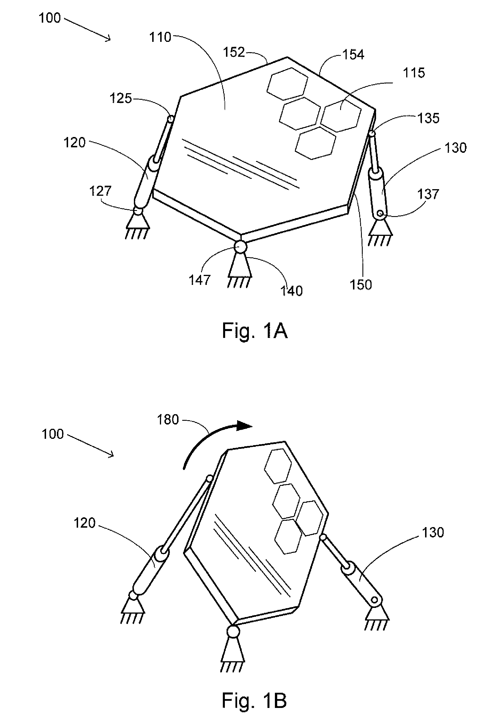
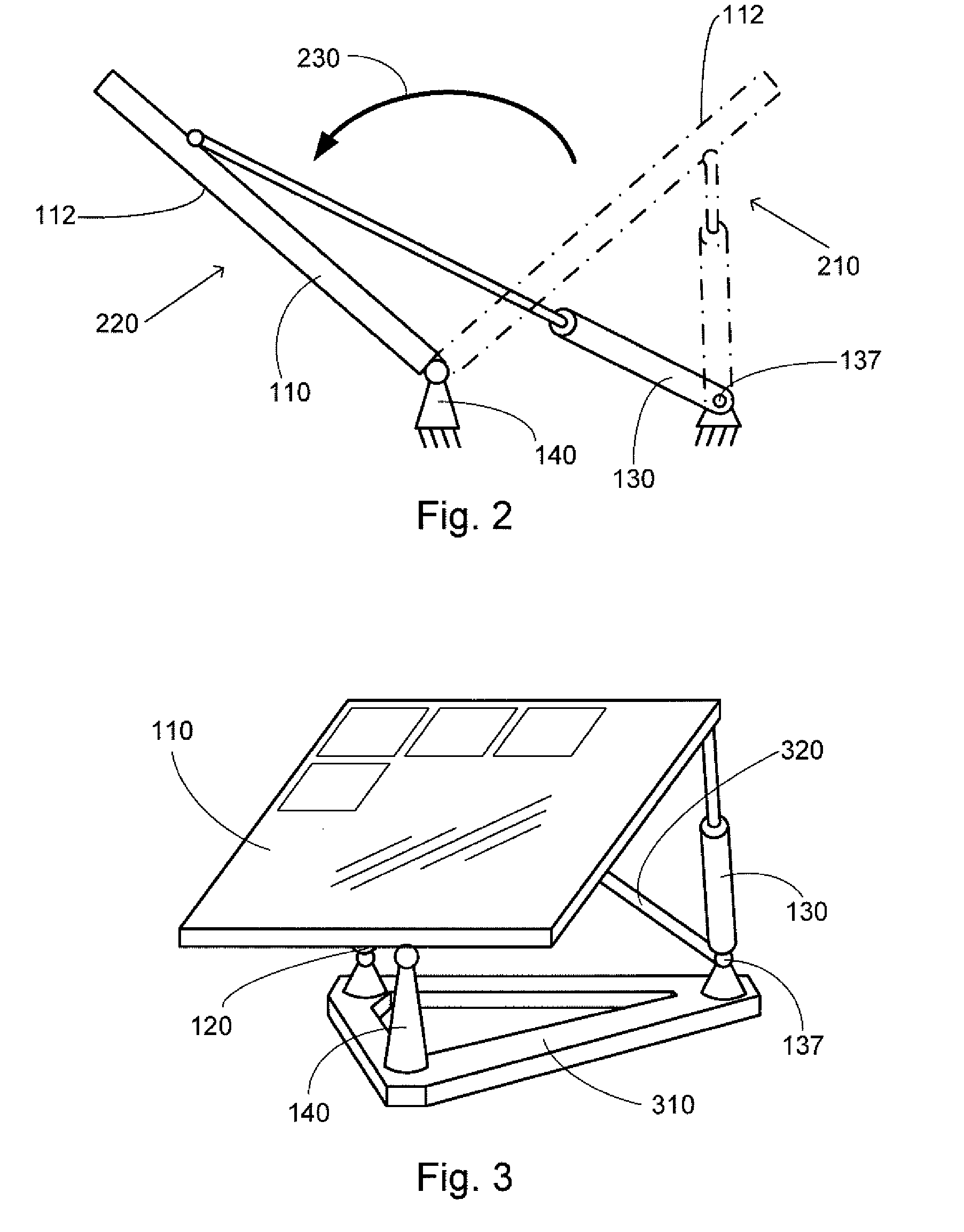
[0017]The current invention provides a low-cost solar tracking system which provides reliable stability with an adequate range of movement to track the sun's movement at various latitudes around the globe. The design of the curr...


PUM


Abstract

The present invention is a solar tracking system which utilizes three supports arranged in a generally tripod configuration. In one embodiment, two of the supports are linear actuators, and the third support is a stationary universally pivoting joint such as a ball and socket joint. The tracking system may include cross-supports for increased stability, a linear rail for additional range of motion, and a mounting base to facilitate installation. This solar tracking system offers a stable, cost-effective design which is also capable of moving the solar module into an optional stowed position.

Description


Claims


Application Information

Patent Timeline
Owner SOLFOCUS
Why Eureka
Try Eureka